
Before installing a UVC germicidal lamp, check what its radiation will reach—not just the area you intend to disinfect. Prolonged or repeated exposure can degrade susceptible plastics. Control the lamp position, exposure time and cumulative dose, and protect nearby components without compromising the required disinfection performance.
There is no universal lamp-to-plastic distance that guarantees safety. A suitable installation depends on the actual UVC light source, its optical output, the material grade and the operating conditions. This applies to both conventional germicidal tubes and a UVC LED lamp enclosed in a tube-shaped housing.
A confirmed case of plastic damage from UVC exposure
The photograph below shows a confirmed case of UVC-related plastic degradation. The damaged area has an uneven surface and visible tearing and material loss. It illustrates why material durability must be considered alongside the intended disinfection function.
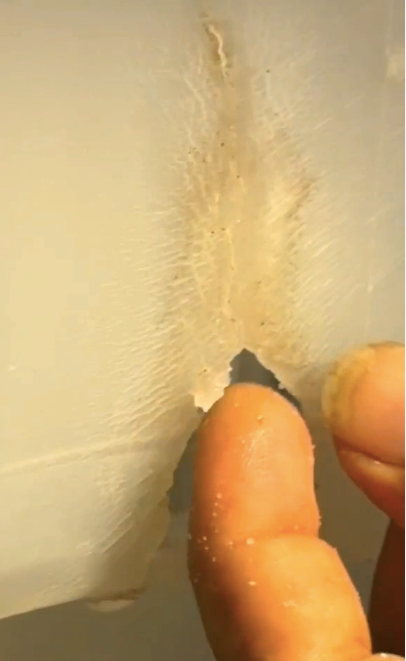
When comparable damage appears in equipment, stop using the affected assembly until its condition and exposure arrangement have been assessed. Moving the lamp does not restore a cracked or weakened component. Replace damaged parts and validate the revised installation before returning it to service.
Why prolonged UVC exposure can damage plastic
UVC exposure can change a polymer’s surface and mechanical properties. Depending on the material and exposure conditions, warning signs may include discoloration, roughening, chalking, cracking or increased brittleness. A component can also deteriorate before obvious visual damage appears. A materials study hosted by NIST found different responses among tested polymers and showed why visual inspection alone is insufficient.
Do not treat all plastics as equally vulnerable—or equally resistant. Ask for compatibility evidence for the specific resin grade, additives, color and finished component under the intended UVC exposure. A general “UV-resistant” description is not enough to establish suitability for this application.
Review seals, cable jackets, adhesives and mounting parts as well as the main plastic housing. A durable tank wall does not prove that every component inside the tank is suitable.
Set distance using measurements rather than a fixed rule
Increasing separation can reduce direct irradiance at a plastic surface, but distance alone does not define its lifetime. The source geometry, beam direction, reflections and exposure duration also matter. Near a long tube or a UVC LED array, do not assume that doubling the distance always reduces irradiance to one quarter. The IUVA discussion of lamp geometry and irradiance explains why near-field and far-field behavior differ.
For a fixed surface under steady illumination:
Radiant exposure (mJ/cm²) = irradiance (mW/cm²) × exposure time (seconds).
Repeated operating cycles add exposure over time. A shorter daily cycle may reduce cumulative exposure, but any change must still meet the validated treatment requirement. A surface-dose calculation is not, by itself, proof of microbial reduction throughout a water tank.
Use a calibrated UVC light meter with a detector suited to the source wavelength and measurement environment. Measure at the relevant surfaces and orientations—not only at a convenient point beside the lamp. A UVC sensor installed elsewhere in the system does not automatically represent the most exposed plastic surface. Opsytec’s measurement guidance distinguishes irradiance from accumulated dose and explains measurement considerations.
Protect nearby materials without blocking the treatment
For a water-system design, consider separating the treatment zone from susceptible plastic components. An enclosed, UVC-compatible flow-through chamber or a properly designed opaque barrier may reduce unwanted exposure. Any barrier must also be evaluated for corrosion, cleanliness, water-contact suitability and reflected radiation.
Do not wrap the lamp in arbitrary material or add a cover without reviewing the optical path. A cover that protects plastic by blocking UVC may also prevent the intended treatment.
A UV-transmitting quartz sleeve is not a UVC shield. It can separate a lamp from water while allowing germicidal radiation to pass through. Its transmission and cleanliness affect the delivered radiation, as described in the EPA UV disinfection guidance.
For UVC LED surface disinfection, shielding must not create untreated areas on the target surface. For water treatment, review flow, mixing, water transmittance, water level and fouling together with lamp placement. Increasing distance to protect a wall is not an acceptable solution if the revised system no longer achieves its treatment objective.
Control operation and prevent human exposure
UVC can injure eyes and skin. Never look directly at an operating germicidal UVC light or expose people to it during inspection. Some UVC lamps can also generate ozone, so confirm the source characteristics and applicable operating precautions. The FDA’s UVC safety guidance describes these hazards.
For enclosed equipment, use shielding and an interlock that switches the source off before access exposes the user. Disconnect power before maintenance; a software command alone is not electrical isolation. Do not bypass an interlock to demonstrate that the lamp works.
Set operating time from the validated process rather than assuming that longer is always better. When selecting a high power UVC LED, assess its optical output and thermal requirements separately from electrical input wattage. More input power does not establish a safe installation or a verified disinfection result.
Validate material life before production
Treat UVC LED disinfection performance and component durability as separate acceptance requirements. A practical development review should cover:
| Check | What to establish |
|---|---|
| Exposure layout | Lamp location, minimum clearances, orientations and reflected exposure |
| Operating cycle | On-time, cycles per day, intended service life and fault behavior |
| Materials | Exact grades of plastics, seals, adhesives and cable insulation |
| Aging tests | Representative exposure, temperature, water chemistry and mechanical stress |
| Acceptance | Agreed limits for cracking, strength, sealing, leakage and treatment performance |
Compare exposed samples with unexposed controls and inspect more than appearance. Recheck mechanical integrity and sealing where these affect function. Accelerated testing needs a justified relationship to real operating conditions; simply increasing lamp intensity does not automatically reproduce years of service.
Repeat the relevant tests after changing the lamp, material, mounting position or operating cycle. Include inspection and replacement instructions in the finished product documentation.
Does a UVC LED sterilizer make every installation safe
No. The term “UVC LED sterilizer” does not establish material compatibility or prove complete sterilization. Claims must match the validated organism, reduction target and operating conditions. A waterproof lamp is also not automatically a complete, validated water-treatment system.
Discuss your UVC lamp integration
For a Three Bears UVC project, send the lamp specification, tank or enclosure drawing, proposed distances, material grades, operating cycle and treatment objective. Include photographs of any existing damage and the available test records.
These details provide a starting point for reviewing lamp placement, material exposure and validation needs. See our waterproof UVC LED lamp integration guide, or send your project requirements.
Send Your Project Requirements