
Application-specific
The module starts from the product geometry and lighting result.
CUSTOM LED MODULE DEVELOPMENT
Develop a custom LED PCB around your product’s board dimensions, LED layout, electrical requirements and thermal conditions. Share your drawings, lighting targets and assembly constraints so we can define the module development scope.
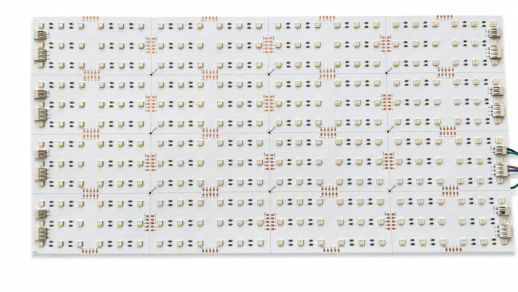
The module starts from the product geometry and lighting result.
Critical optical, thermal, and assembly assumptions are checked.
Acceptance points are defined for the agreed application.
Approved requirements follow the design into assembly and test information.
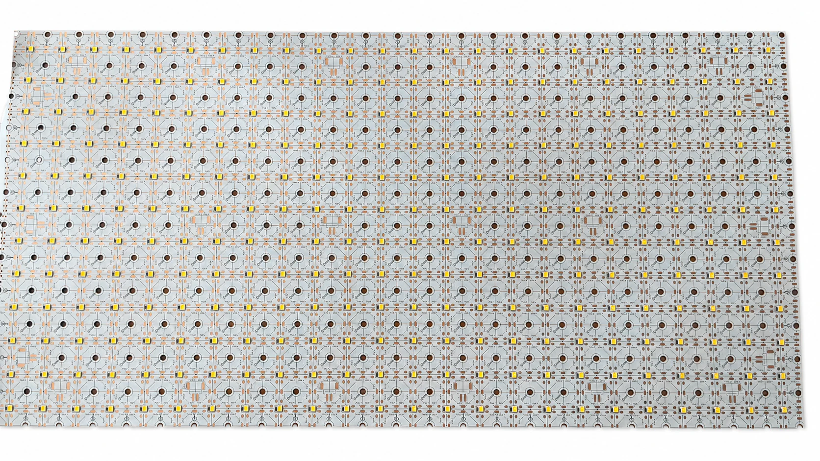
ONE PROJECT, ONE CONFIRMED SPECIFICATION
The LED board, drive conditions, optics, thermal path, connectors, mounting, and surrounding structure need to work as one system.
APPLICATION-LED DEVELOPMENT
The same LED can behave differently when board material, copper area, operating current, heat transfer, spacing, optics, enclosure geometry, and ambient conditions change. A custom module must therefore be considered inside the product rather than as an isolated PCB.
A project can begin from mechanical drawings, optical targets, a driver specification, Gerber files, an existing fixture or module, photos, samples, or a structured requirements list. Final component choices, measurable criteria, deliverables, approval gates, and schedule are confirmed after the available inputs are reviewed.
COMMON PROJECT DIRECTIONS
These application-specific directions require separate electrical, optical, thermal, mechanical, and validation inputs. VCSEL work is treated as an optical-module project rather than an LED product.
CYCLING / BACKPACK LIGHTING
5V power-bank supply, left/right turn signals, red brake strobe and green or RGB meteor riding effects. Handlebar button remotes can be customized.
Cycling Backpack LED Strips — View details →01 / BACKLIT STONE
Board geometry, LED spacing, drive conditions, heat paths, and optical uniformity can be reviewed for translucent stone and decorative panels.
LED panels for stone backlighting — View details →02 / AUTOMOTIVE AMBIENT
Rigid or shaped modules can be reviewed around light guides, mounting, wiring, color behavior, and the vehicle-specific project requirements.
Automotive ambient lighting modules — View details →03 / UVC
Wavelength, irradiance target, thermal path, optics, enclosure, exposure controls, and validation requirements must be defined for the application.
UVC LED modules — View details →04 / UVC LED STRIPS
Flexible geometry, segment layout, electrical drive, thermal path, shielding, materials, and application-level dose validation need to be reviewed together.
UVC LED strips — View details →05 / REPTILE UVB
Spectrum, irradiance distribution, working distance, thermal conditions, and fixture geometry need project-specific review.
Reptile UVB LED modules — View details →06 / OPTICAL MODULES
Emitter selection, drive conditions, thermal path, optics, interfaces, and safety requirements can be evaluated as a separate optical-module project.
VCSEL optical modules — View details →DESIGN DECISIONS WE CONFIRM
Targets that are not yet known remain questions for the project brief; they are not converted into unsupported performance claims.
Outline, thickness, keep-outs, mounting, LED positions, and available product space.
Voltage, current, circuit arrangement, dimming method, and driver relationship.
Color, CCT, CRI, output, uniformity, or other application-specific priorities.
Board material, copper, heat spreading, product interfaces, ambient, and duty cycle.
Diffusers, lenses, reflectors, spacing, visible surfaces, and assembly clearances.
Polarity, wires, terminals, connectors, test points, and agreed acceptance criteria.
ENGINEERING FOCUS
PRODUCT GEOMETRY
The available area, mounting points, visible surface, optical parts, cable route, and service access influence the board outline and LED positions.
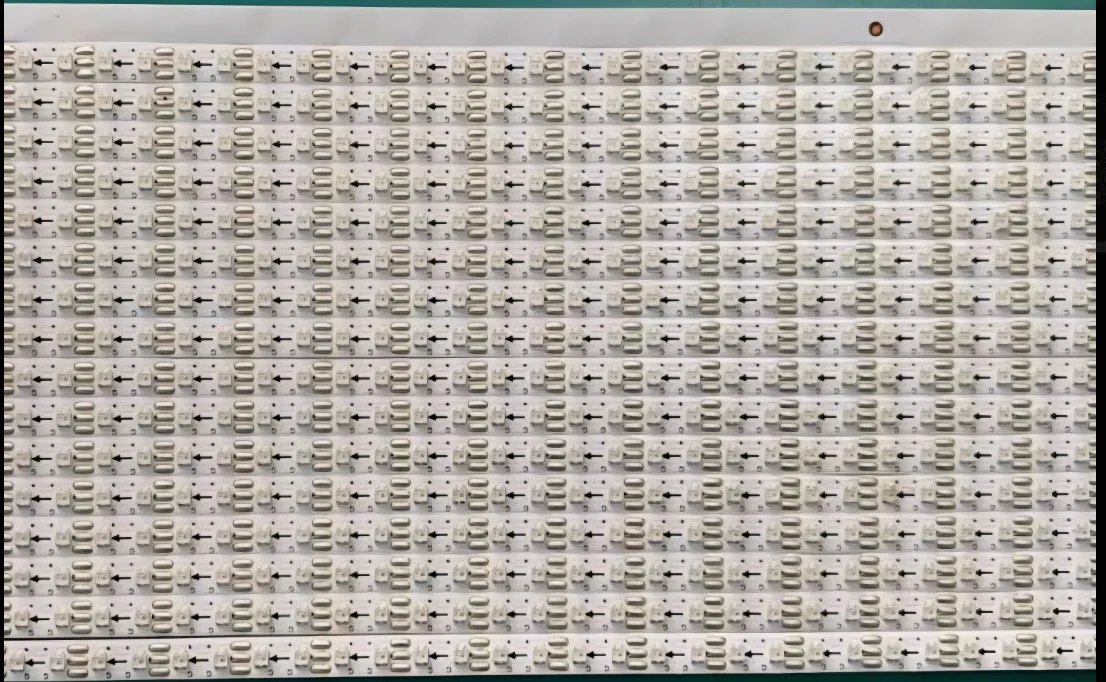
LIGHT & HEAT
LED selection and operating point cannot be separated from board construction, heat transfer, ambient conditions, optics, and the intended visual result.
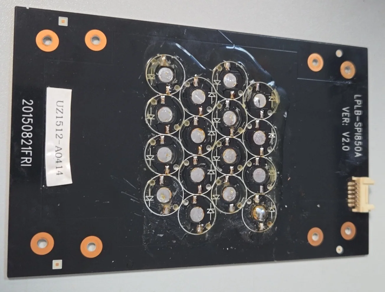
PROTOTYPE REVIEW
Prototype review can address electrical operation, optical appearance, thermal behavior, physical fit, connectors, and assembly questions selected for the project.
REVIEW FOCUS
DOWNSTREAM ASSEMBLY CONTEXT
These images show real lighting wiring assembly and packing environments. They do not represent PCB fabrication or prove a module test result.
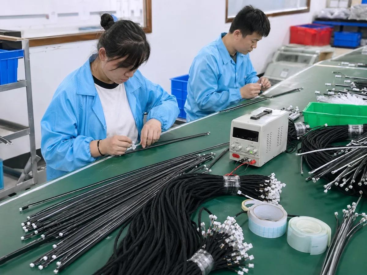
Where relevant to the agreed scope, wiring, connectors, polarity, handling, and assembly instructions can follow the approved module information.
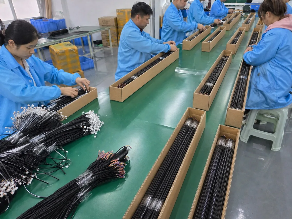
Where relevant, labeling and packing details can be organized with agreed inspection points and approved production information.
Exact assembly, inspection, testing, documentation, and delivery activities are confirmed for each project; no result or capability beyond the agreed scope is implied.
CONTROLLED PROJECT PATH
Each stage produces a clearer decision point. A prototype or review result is not treated as production approval.
Review product geometry, electrical and optical targets, thermal context, available files, and open questions.
Develop the agreed LED configuration, board construction, layout, connections, and sample route.
Check the agreed electrical, optical, thermal, mechanical, and assembly criteria, then revise where required.
Release the approved design information, sourcing, assembly, inspection, labeling, and packing requirements.
RFQ CHECKLIST
You do not need every answer before contacting us. Mark confirmed requirements, preferred targets, and items that still need engineering review.
FREQUENTLY ASKED QUESTIONS
The answers below clarify the starting process without promising an unreviewed construction, output, certification, or schedule.
Share available mechanical drawings, board outlines, schematics, BOM, Gerber files or reference samples, together with driver conditions, lighting targets, thermal context, quantity and target date. A custom LED board project can also start from a requirements list; missing inputs are identified during review.
PCB design is carried out in-house. LED PCB assembly and manufacturing activities are coordinated with partner factories when included in the agreed project scope. Confirm component sourcing, prototype quantities, inspection criteria and production handoff requirements before starting.
Custom outlines and LED locations can be evaluated against electrical, thermal, optical, mechanical, and manufacturing constraints. The final geometry is confirmed for the specific project.
Yes. Clear photos, dimensions, labels, driver details, known operating conditions, existing files, and the reason for changing the current design can provide a useful starting package.
The module circuit and operating point need to be reviewed with the intended driver and product power architecture. Unknown electrical conditions must be resolved before the design is approved.
Optical targets can be included in the project inputs. Feasibility, component selection, tolerances, measurement method, optics, and acceptance criteria must be confirmed for the application.
The review can include board material, copper, LED operating point, product heat path, ambient conditions, airflow, enclosure, duty cycle, and the agreed verification method.
Evaluation points are selected for the project and may include electrical operation, optical appearance, thermal behavior, physical fit, connectors, polarity, or assembly. A sample is not automatically a production approval.
A first review can begin from either, but the information required for a reliable scope and quotation depends on the open electrical, optical, thermal, mechanical, and production questions.
PROJECT INQUIRY
Include the application, geometry, electrical and optical targets, expected quantity, target date, and supporting files. Open questions are welcome.