Wavelength & emitter
Target wavelength range, spectral requirements, package, bin, optical data, supplier information, and traceability.
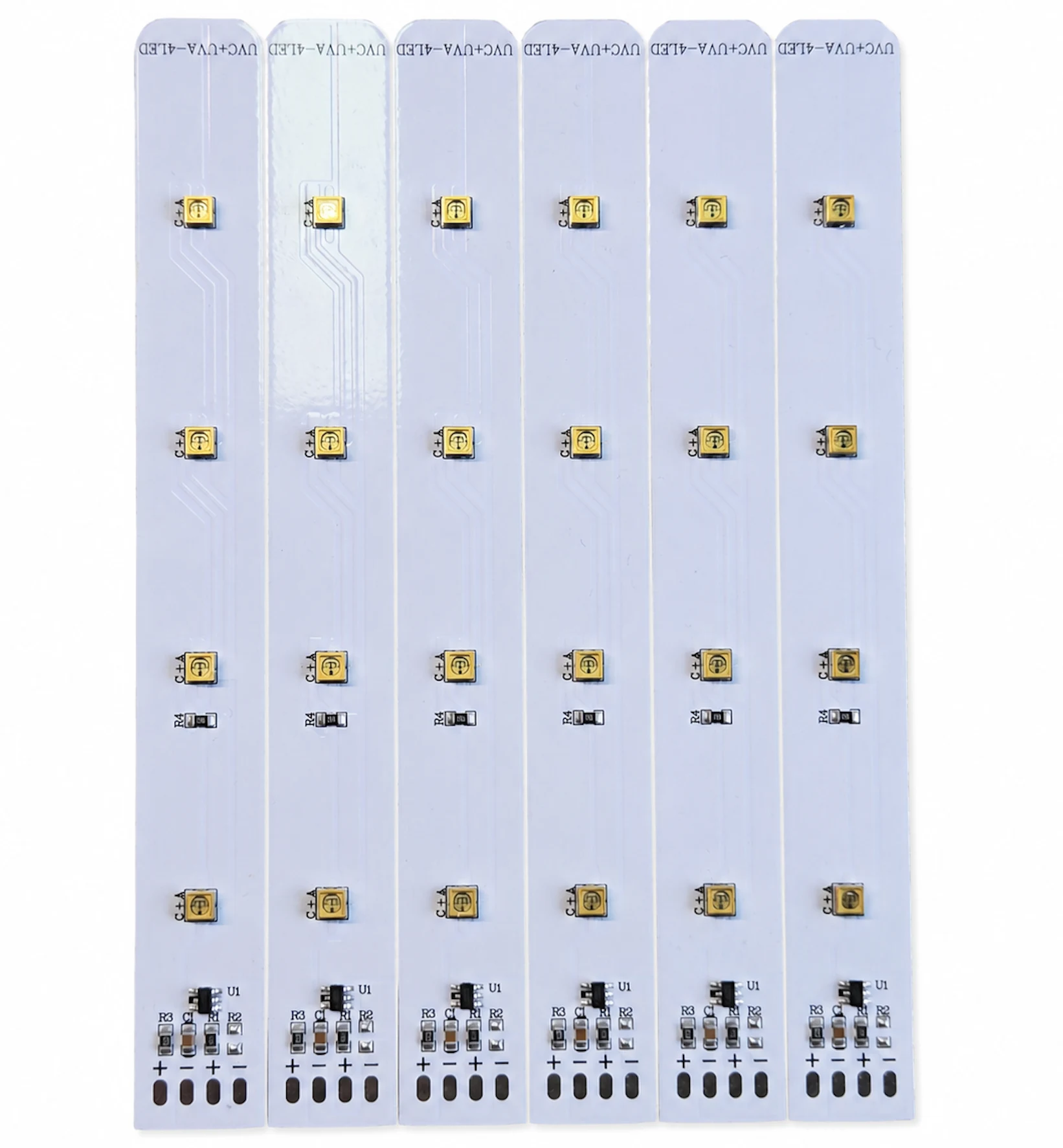
UVC LED MODULE DEVELOPMENT
Develop a UVC LED board around the required wavelength, emitter layout, drive conditions and thermal path. Share the enclosure, exposure geometry and validation requirements so we can review the module and system integration scope.
Switch this illustration on or off. No physical device is connected.
Illustration OFF · Physical hardware is not connected.
This diagram does not show actual irradiance, dose, wavelength, LED placement or disinfection performance. Confirm the selected product and validate the complete system. Disconnect power before access or servicing.
UV safety information — FDA ↗Wavelength and application geometry confirmed first
Optical output, thermal path, driver, and materials reviewed together
Dose and disinfection claims require application-specific validation
Review the inputs needed to start
↓APPLICATION FIRST
UVC LED performance depends on wavelength, electrical operating point, junction temperature, optics, distance, angle, exposure time, target surface or flow path, fouling, aging, and surrounding materials. The module must be evaluated inside the actual water, air, or surface system.
APPLICATION GUIDE
Review enclosure, delivered dose, water-path geometry, materials, thermal control, maintenance, and UVC exposure safety before finalizing the installation.
Read the waterproof UVC lamp guideDESIGN REFERENCE
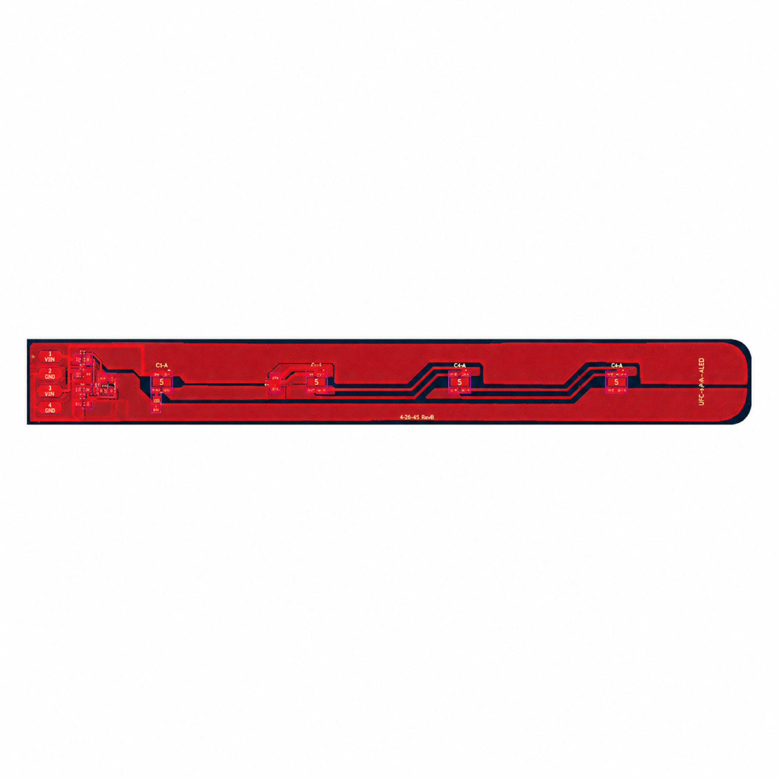
Presentation image only. Fine markings and traces may differ from the original engineering files. Not a fabrication file or wiring guide.
DEFINE BEFORE DESIGN
Confirmed requirements, preferred targets, and open questions can all be included in the first brief. Unknown values stay visible until they are reviewed.
Target wavelength range, spectral requirements, package, bin, optical data, supplier information, and traceability.
Target area or flow path, distance, angle, residence time, shadowing, reflectors, windows, sleeves, and fouling.
Current, voltage, series or parallel arrangement, driver method, dimming or pulsing, monitoring, and fault behavior.
Board material, copper, heat spreader, interface, enclosure, ambient or fluid temperature, airflow, and duty cycle.
UVC exposure of plastics, seals, adhesives, cables, optics, water-contact parts, shielding, interlocks, and user access.
Irradiance or dose measurement, test geometry, aging, migration or shedding where relevant, microbiological method, and acceptance criteria.
MODULE FORMAT
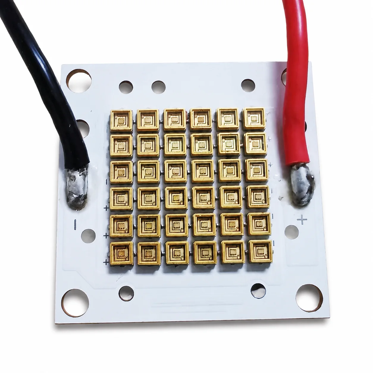
The photograph shows another module format from the available product-image set. It does not establish wavelength, output, performance, qualification, or application suitability.
Review your module formatPROJECT FIT
Application claims stay conditional until the complete system, operating conditions, and agreed validation method are tested.
Flow path, optical access, sleeve or window, thermal conditions, wetted materials, sensing, and dose validation.
Airflow, residence time, shadowing, reflective chamber, thermal path, containment, and maintenance.
Distance, uniformity, target coverage, timing, shielding, interlocks, and verified test method.
Separate wavelength roles, drive conditions, optical paths, thermal load, timing, and validation criteria.
CONTROLLED DEVELOPMENT PATH
A review result, prototype, or sample remains a project stage. Production begins only from the information and acceptance criteria approved for that project.
Confirm geometry, electrical input, optical target, thermal conditions, quantity, and the available source material.
Define the board, emitter arrangement, drive conditions, connections, mounting, and prototype route.
Review the agreed electrical, optical, thermal, mechanical, and safety-related acceptance points.
Carry the confirmed design, BOM, assembly, inspection, labeling, and packing information into production.
DESIGN & MANUFACTURING SUPPORT
Our in-house PCB design connects your product requirements with manufacturing and testing capabilities at our partner factories.
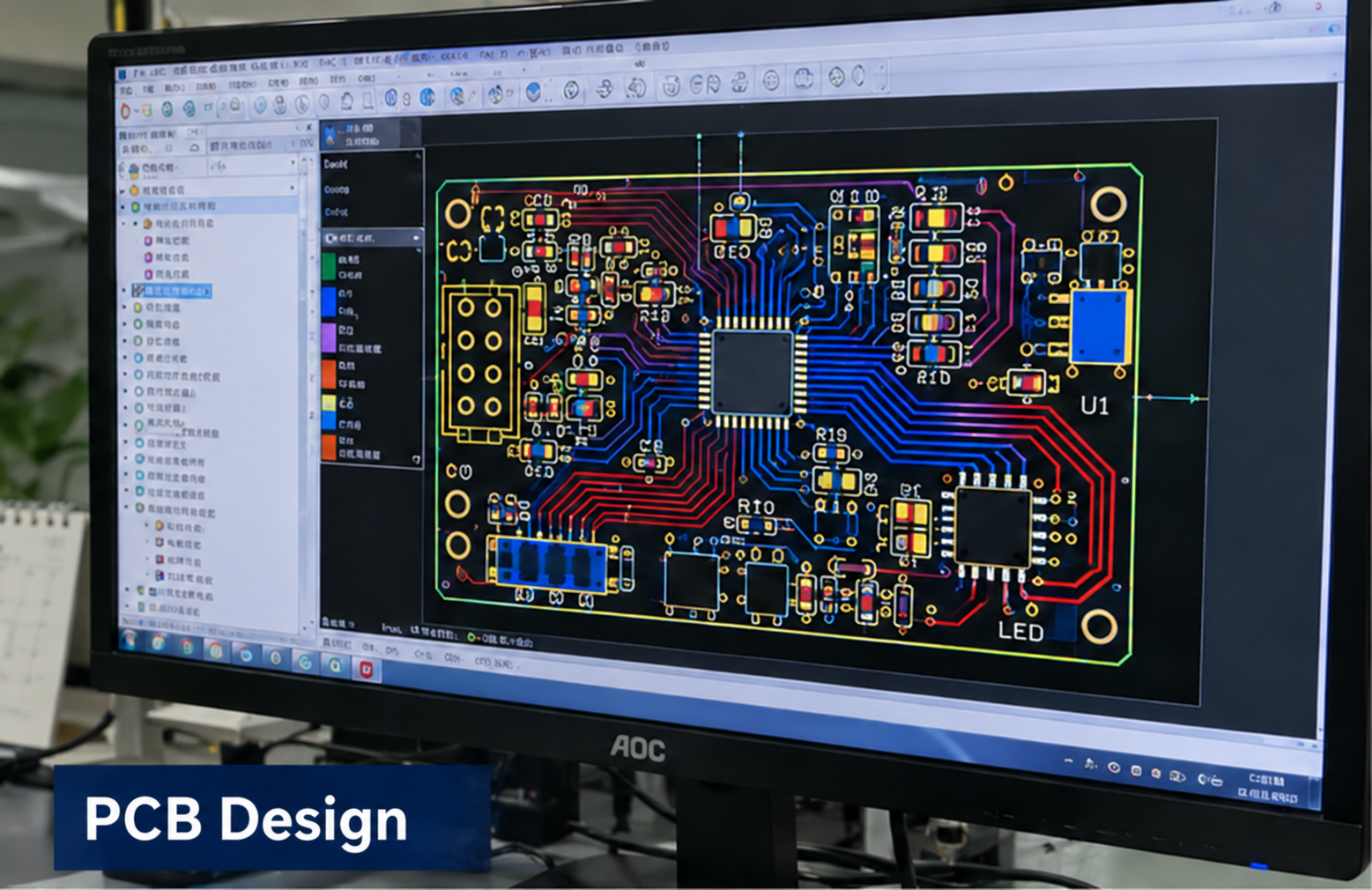
In-house design
Circuit and PCB layout developed around your product requirements.
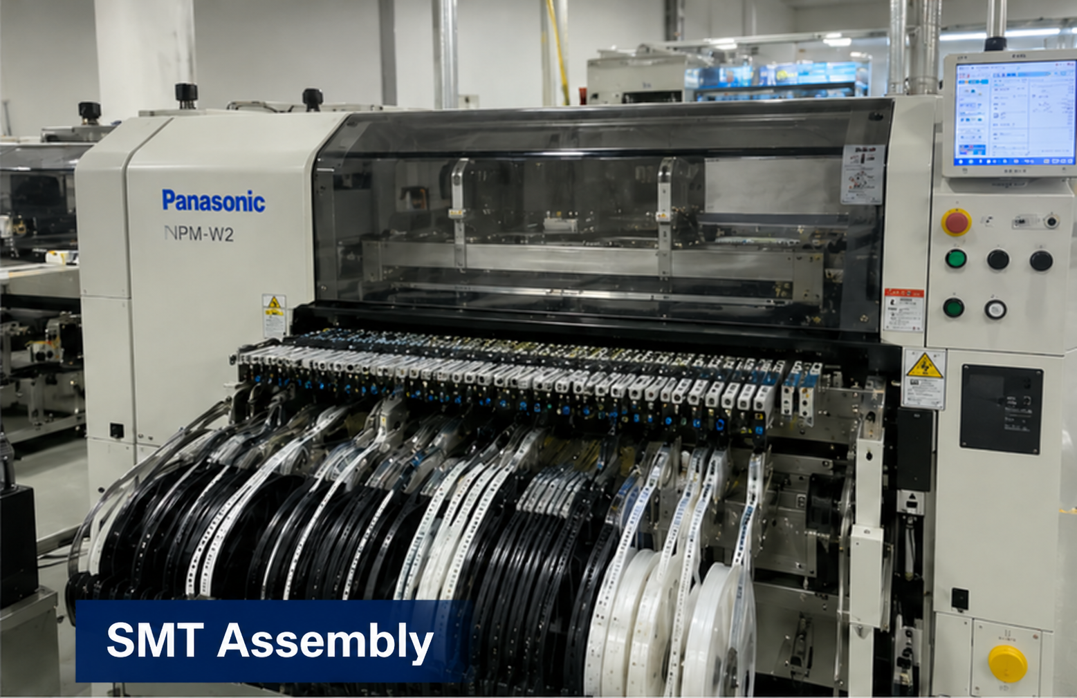
Partner factory
Component placement and assembly for the approved board design.
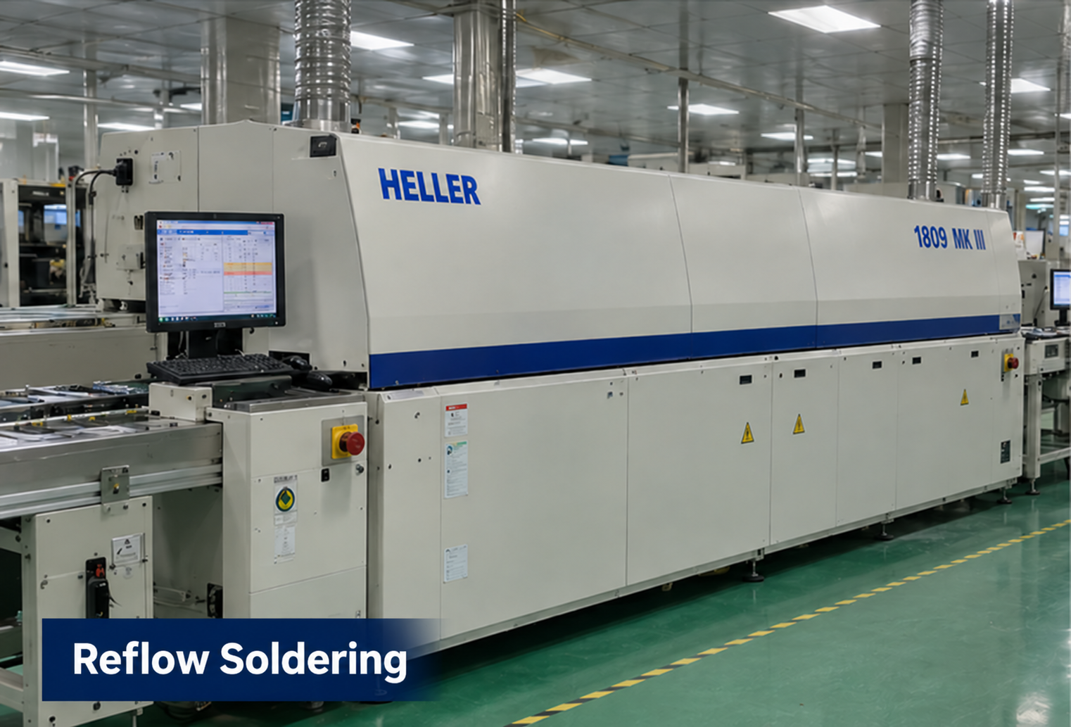
Partner factory
Reflow soldering as part of the board assembly process.
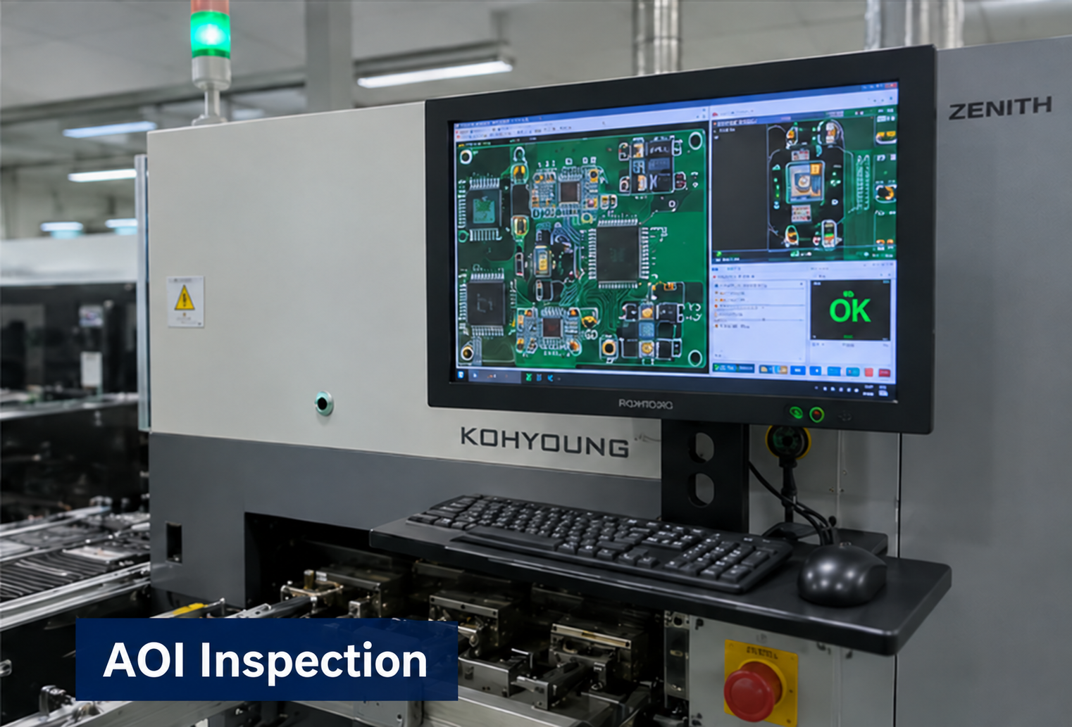
Partner factory
Optical inspection to support assembly quality checks.
Partner factory
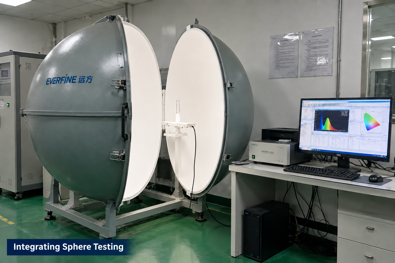
Optical measurement for applicable LED module projects.
Manufacturing and testing scope is agreed for each project. Integrating sphere testing applies to LED optical projects; it is not a required test for every control board. These images illustrate capabilities, not test results or certification for this product.
PROJECT QUESTIONS
These answers describe how a project can begin. They do not promise an unreviewed specification, performance result, certification, schedule, or price.
No guarantee should be made from the module alone. The organism, dose, wavelength, distance, flow or exposure time, shadowing, fouling, aging, measurement method, and complete system must be validated.
Direct UVC exposure can degrade many polymers and seals. The exact resin, additives, wavelength, irradiance, temperature, exposure time, water-contact requirements, aging, migration, and particle shedding need review. Structurally blocking unnecessary line-of-sight is often the safer starting point.
Provide LED operating current, duty cycle, board construction, heat spreader, thermal interface, enclosure, airflow or fluid temperature, ambient range, and the intended temperature measurement points.
Send the application, target wavelength, chamber or product geometry, target area or flow, driver conditions, materials, thermal path, sensors and interlocks, expected quantity, target date, and required validation method. The UVC LED PCB layout is reviewed against these system requirements.
RECOMMENDED READING
Before placing a UVC LED module near plastics, review the confirmed damage case and how distance, cumulative exposure and material compatibility affect integration.
Read the UVC safety articlePROJECT INQUIRY
Include the application, confirmed inputs, preferred targets, expected quantity, target date, and available drawings, photos, files, or samples.
Inquiry about: UVC LED Modules