
MODE · short press
Release to select the next effect. The 15-second timer restarts and automatic playback continues through all 84 effects.
5V TYPE-C CHARGING · ADDRESSABLE RGB
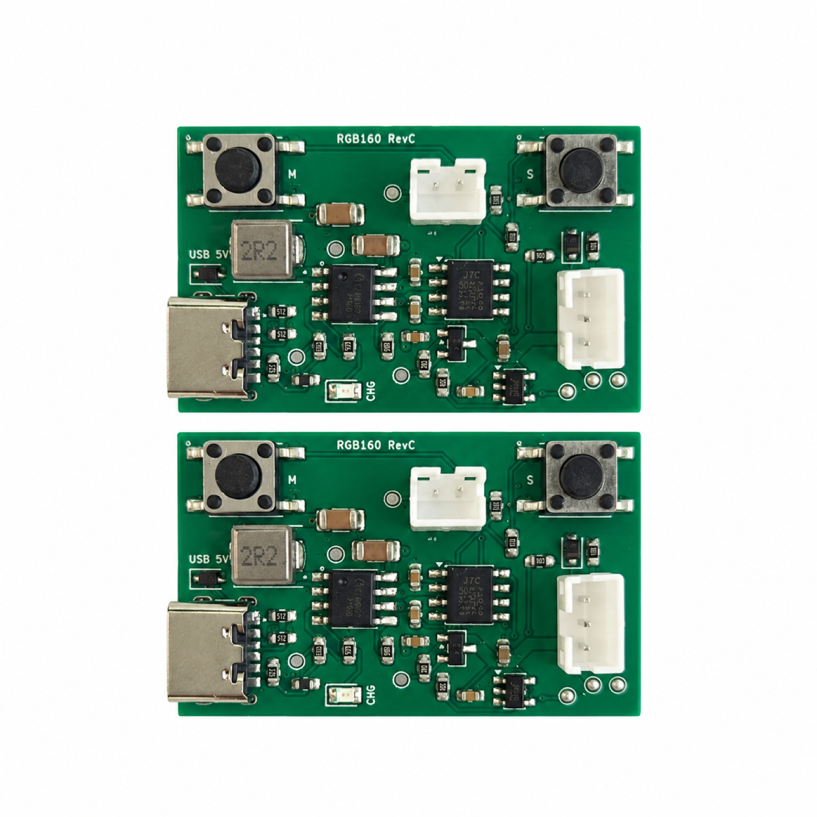
Bring addressable RGB effects to portable ambient lighting. This compact 40 × 25 mm controller combines 5V Type-C charging with battery operation and two-button control. The current reference firmware drives 160 WS2812B LEDs and cycles through 84 lighting effects.
Press M to change the RGB effect. Press S to adjust its speed.
M cycles Rainbow flow → RGB meteor → Color chase → Color breathing. S cycles from slow to fast, then returns to slow.
Illustrative effects only, not a recording of the controller firmware. These four previews and five speed levels are for this web demo; actual effects, speed settings and LED count depend on the selected firmware.
5V Type-C charging · battery operation
160 WS2812B LEDs · 84 effects · 15-second autoplay
Two buttons · five speed and brightness levels
Review the inputs needed to start
↓APPLICATION FIRST
The reference design uses a 40 × 25 mm PCB, a PH2.0 2-pin battery connector and a PH2.0 3-pin LED connector. Charging indication and power-path management are handled by the charging hardware. The current V4 firmware provides automatic effect playback, manual mode selection, speed adjustment, dimming and soft on/off. Effects and control behavior can be customized for the approved LED load and application.
REFERENCE CONFIGURATION
This board does not boost battery voltage to a regulated 5V LED output. Use a battery with an external protection circuit. Software low-voltage shutdown does not replace battery, short-circuit or overcurrent protection. V4 has passed software checks; final-board operation, charging under load, temperature and low-voltage behavior still require physical validation.
BUTTONS & PLAYBACK
Current V4 reference behavior for the 160-LED configuration. Short presses act on release; long presses act once per hold. Final operation must be verified on the selected board and LED load.
Release to select the next effect. The 15-second timer restarts and automatic playback continues through all 84 effects.
Turn the LEDs on or off. A continuous hold triggers only once. Mode, speed and brightness are retained during the same powered session.
Release to cycle through five animation speeds, from slow to fast and back. Speed does not change the 15-second autoplay interval.
Cycle through five brightness levels: approximately 6%, 16%, 31%, 56% and 100%. Each long press advances one level.
After a complete power cycle and a stable supply, start with a rainbow-trail effect and change every 15 seconds. All 84 effects repeat in approximately 21 minutes. Default speed is level 3 and brightness is approximately 31%.
Autoplay pauses while the LEDs are off. Complete power loss restores defaults; settings are not stored in nonvolatile memory. If the battery remains connected and the LEDs are off, inserting USB may not restart the board; hold MODE to turn on.
REFERENCE MEDIA
Three supplied white-background views of the controller. These presentation images do not establish pin assignments or validate electrical performance.
01 / BOARD OVERVIEW
Compact controller layout with MODE and SPEED keys, charging indication and separate battery and LED connectors.
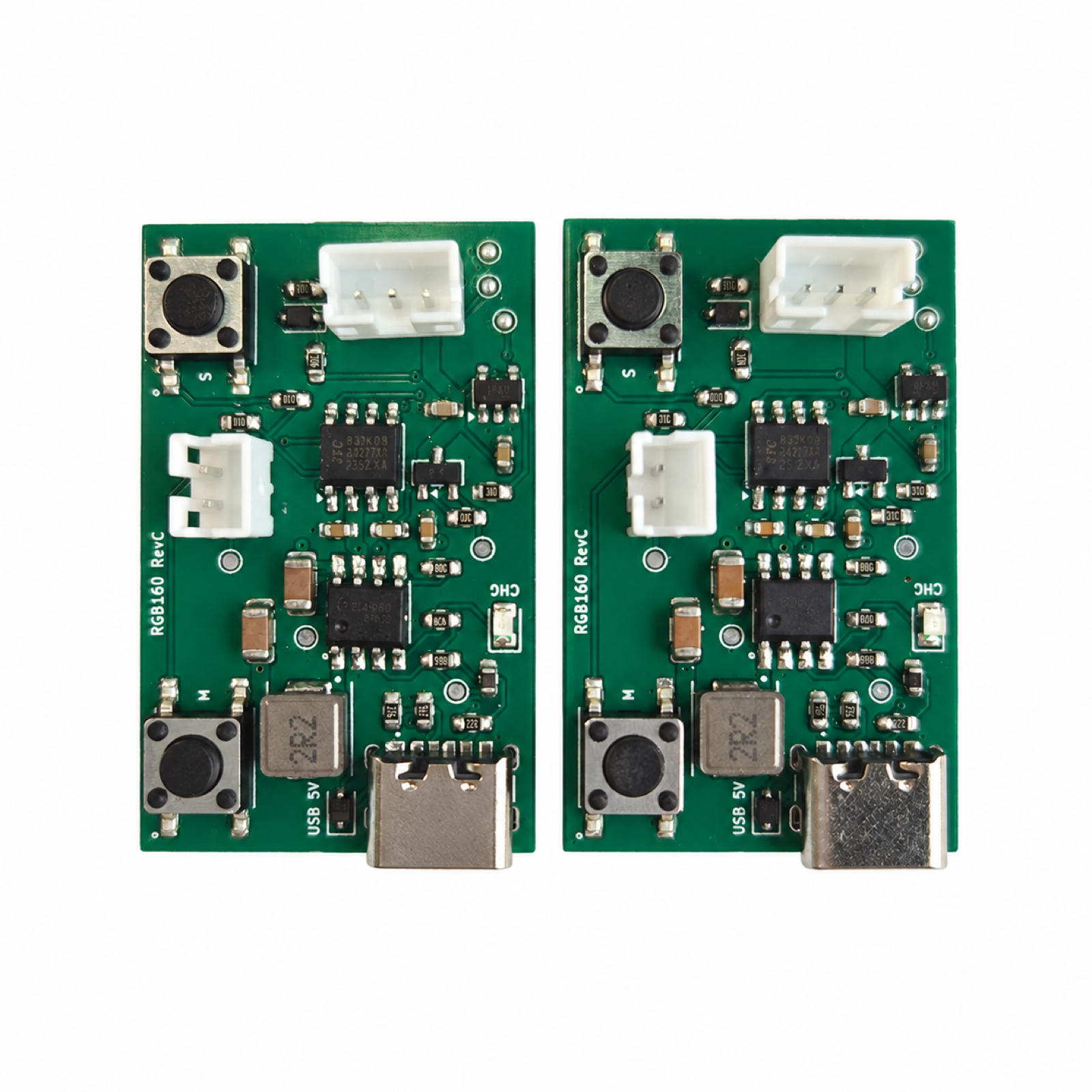
02 / CONNECTOR VIEW
PH2.0 2-pin battery and 3-pin LED interfaces. Verify polarity and the approved connector pinout before connection; do not infer it from a presentation image.
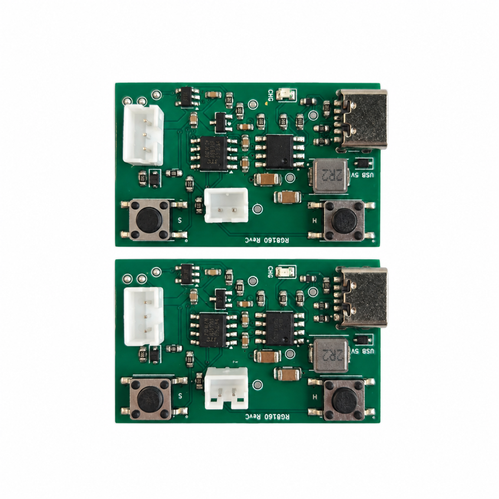
03 / ALTERNATE VIEW
Allow access to the Type-C port and both buttons, and provide clearance for connectors, wiring and the final enclosure.
LIGHTING EFFECT DEMONSTRATION
Supplied footage shows a controller, battery and illuminated RGB strip. This short demonstration illustrates lighting appearance; it does not verify all 84 modes, runtime, charging performance or protection behavior.
PROJECT FIT
A starting point for rechargeable decorative products. Confirm the LED protocol, battery, wiring, enclosure and measured power budget for each application.
Battery-powered accents with accessible charging and simple two-button operation.
Addressable effects integrated into bags, props or decorative accessories, subject to enclosure and battery validation.
Automatic color sequences for compact displays and illuminated frames.
Review effect sequences, timing, startup behavior and LED count against the selected hardware and firmware capacity.
CONTROLLED DEVELOPMENT PATH
A review result, prototype, or sample remains a project stage. Production begins only from the information and acceptance criteria approved for that project.
Confirm the application, functions, electrical limits, interfaces, mechanical constraints, quantity, and open questions.
Develop the agreed circuit, PCB layout, firmware scope, connectors, and prototype route.
Check the agreed functional, electrical, thermal, communication, and fit criteria, then record revisions.
Release only the approved design, component, firmware, assembly, inspection, and packing information.
DESIGN & MANUFACTURING SUPPORT
Our in-house PCB design connects your product requirements with manufacturing and testing capabilities at our partner factories.
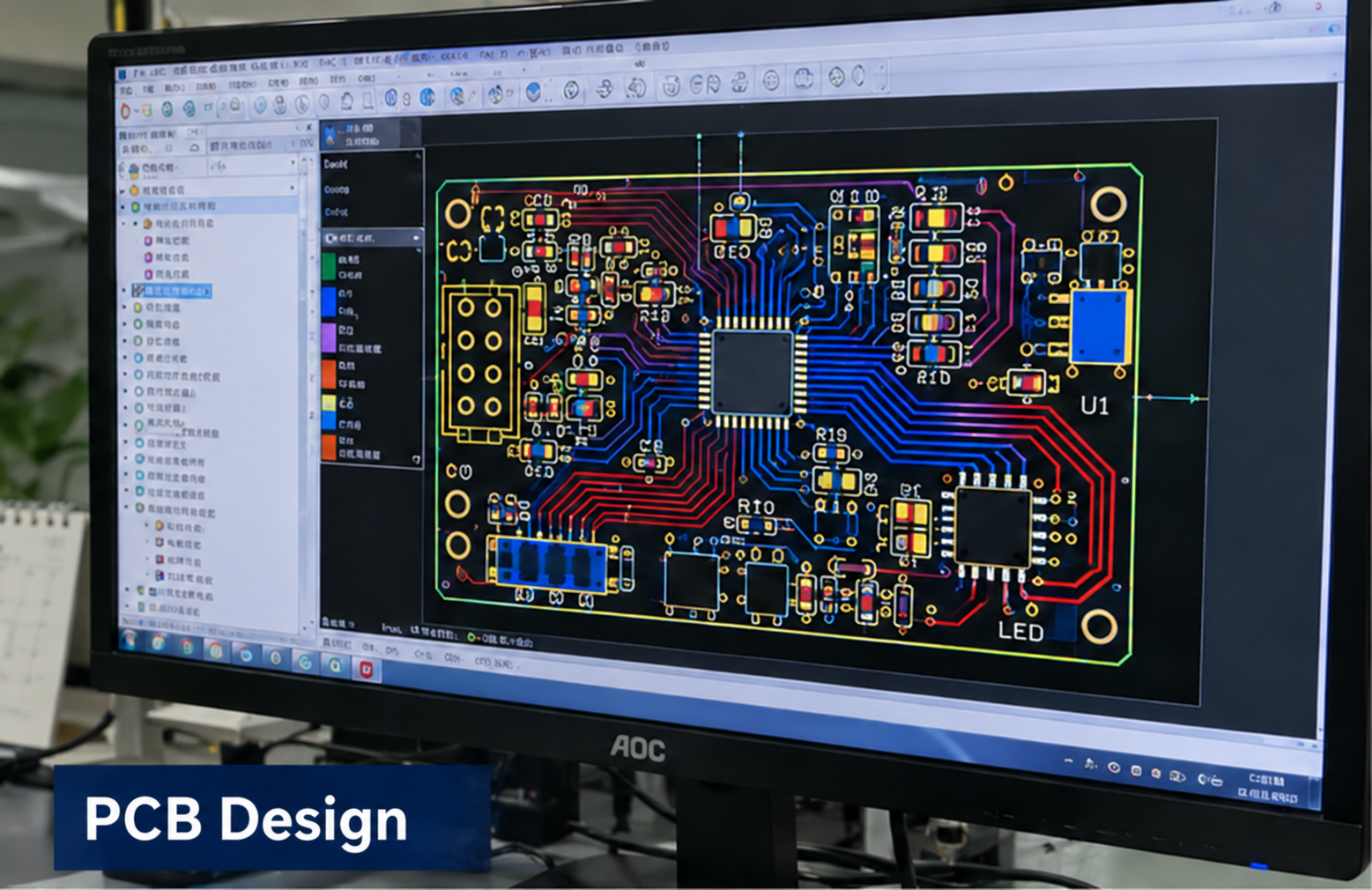
In-house design
Circuit and PCB layout developed around your product requirements.
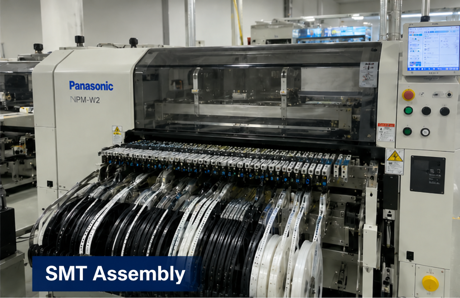
Partner factory
Component placement and assembly for the approved board design.
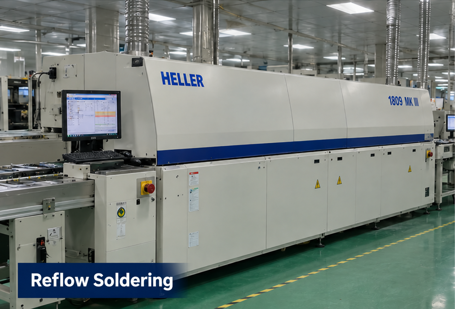
Partner factory
Reflow soldering as part of the board assembly process.
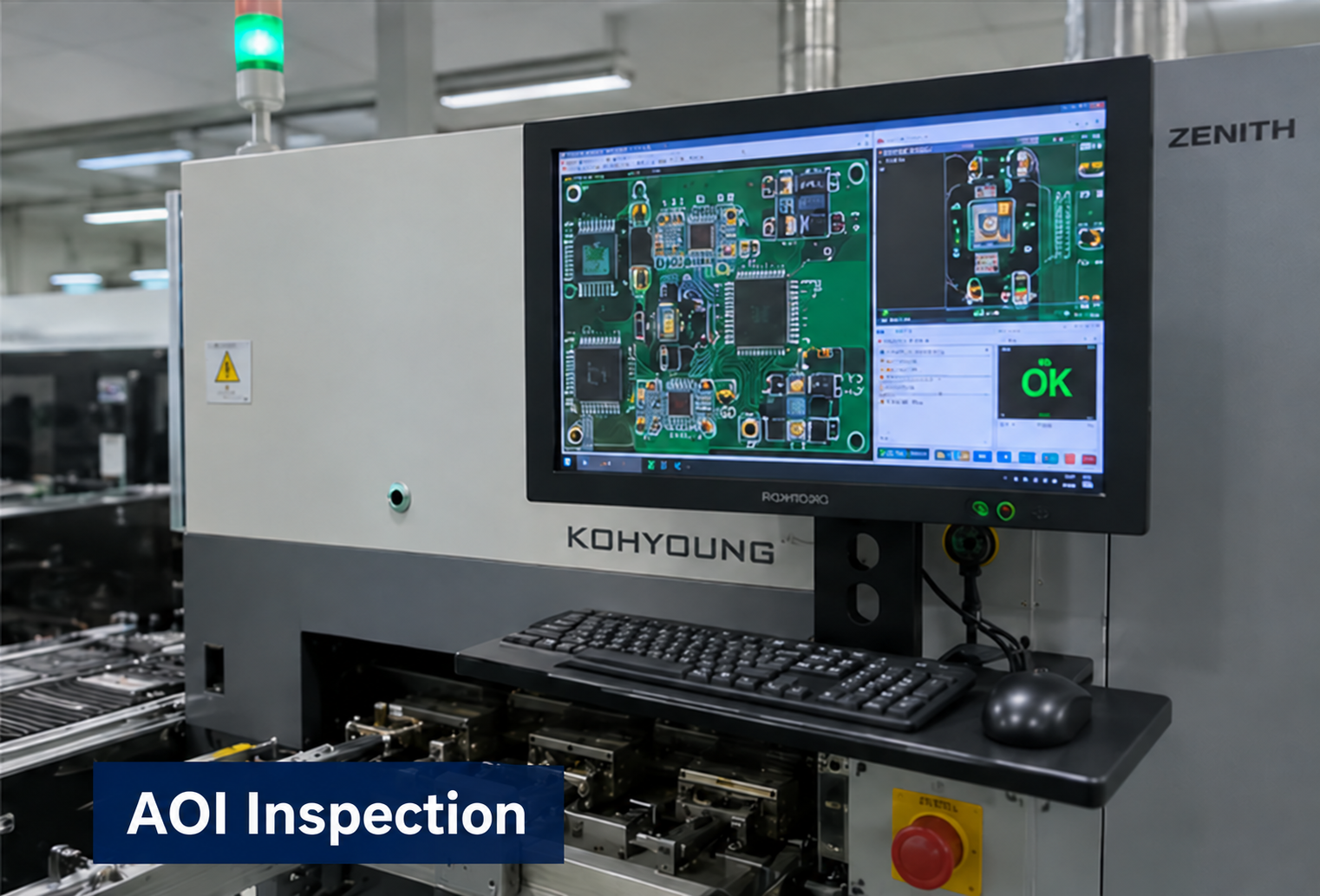
Partner factory
Optical inspection to support assembly quality checks.
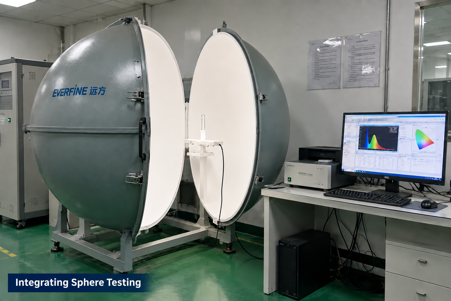
Partner factory
Optical measurement for applicable LED module projects.
Manufacturing and testing scope is agreed for each project. Integrating sphere testing applies to LED optical projects; it is not a required test for every control board. These images illustrate capabilities, not test results or certification for this product.
PROJECT QUESTIONS
These answers describe how a project can begin. They do not promise an unreviewed specification, performance result, certification, schedule, or price.
The current reference firmware is configured for 160 WS2812B LEDs in GRB order. Other protocols, LED counts and loads need a separate compatibility and power review. It is not a universal analog RGB or RGBW controller.
No. Type-C is the 5V charging input, and the board has no battery-to-5V boost stage. LED voltage follows the power-path supply conditions. Check LED behavior across the battery operating range.
Yes, subject to hardware and firmware capacity. The V4 reference offers 84 modes, each played for 15 seconds, including rainbow trails, color animations and red, green and blue steady modes. There is no full-white mode in this reference firmware.
No. A soft off/on retains the current mode, speed and brightness while power remains connected. A complete power loss restores defaults.
No. The firmware monitors the controller supply and switches the LEDs off after sustained low voltage; it does not directly measure the battery terminal. Actual thresholds require board testing. Use an externally protected battery and validate charging current, temperature, load and fault behavior.
Send the LED model and count, current data, protected battery specification, target runtime, desired effects, connector pinout, enclosure dimensions and quantity. Charging and simultaneous operation must be validated with the actual battery and load.
RECOMMENDED READING
Review the strip IC, signal interface, pixel configuration and power path before selecting a controller. Use the symptom checklist to plan the next test.
Read the compatibility guidePROJECT INQUIRY
Include the application, confirmed inputs, preferred targets, expected quantity, target date, and available drawings, photos, files, or samples.
Inquiry about: Type-C Rechargeable RGB Controller