Left turn
Directional light effect for a left-turn command.
5V POWER BANK · TURN & BRAKE SIGNALS
Integrate a 5V LED strip into your cycling backpack for left and right turn signals, a red brake strobe, and green or RGB meteor riding effects. Share the backpack layout, power-bank arrangement and rider-control requirements for OEM integration review.
Choose a button to animate the LEDs on the product photo.
Steady green illumination for normal riding.
Flashing-light warning: the brake effect flashes red. Animation starts only on request; pause at any time.
LED sequence and timing sampled from the supplied demonstration. Turn and brake glow is enhanced for visibility. Photo-based visualization, not a brightness or firmware timing measurement.
Demo controls only. A handlebar-mounted button remote can be customized.
View the actual demo video5V power-bank supply
Left / right turn · red brake strobe
Green / RGB meteor · custom handlebar remote
Review the inputs needed to start
↓APPLICATION FIRST
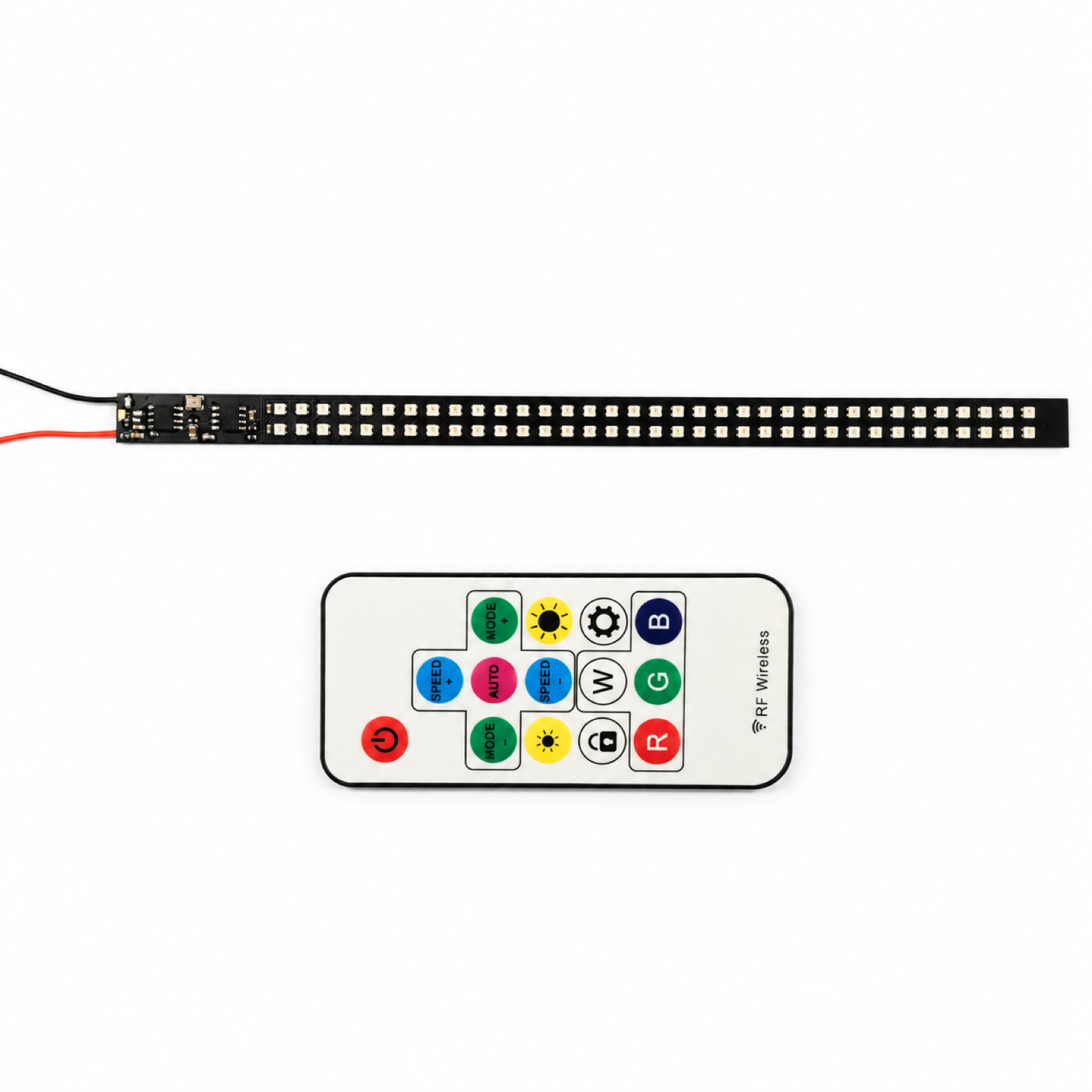
Combine normal riding illumination, directional signals and a braking light effect in one strip. Define the mounting orientation, cable routing and rider controls around the backpack. The demonstration remote is not the proposed handlebar control.
APPLICATION NOTE
The pictured remote is for demonstrating effects. Handlebar button remotes can be customized. This page does not establish automatic brake sensing, a waterproof rating or road-use certification; finished-product suitability requires separate review.
DESIGN REFERENCE
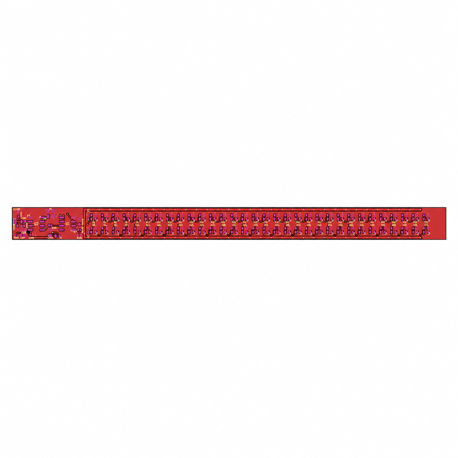
Presentation image only. Fine markings and traces may differ from the original engineering files. Not a fabrication file or wiring guide.
RIDING FUNCTIONS
Choose the normal riding look and define how turn and brake commands take priority.
Directional light effect for a left-turn command.
Directional light effect for a right-turn command.
Red strobe effect. Trigger method to be confirmed.
Green illumination or RGB meteor effects.
DEFINE BEFORE DESIGN
Confirmed requirements, preferred targets, and open questions can all be included in the first brief. Unknown values stay visible until they are reviewed.
Use a 5V power bank. Confirm output current, connector, cable and power-bank auto-shutoff behavior for the final assembly.
Confirm strip dimensions, mounting position, diffuser or cover, cable routing and strain relief.
Support left and right turn effects. Agree on orientation, activation, cancellation and return to normal riding mode.
Red strobe is the specified brake effect. Confirm how braking is triggered; automatic brake detection is not specified.
Handlebar-mounted button controls can be customized. Confirm mounting, button assignments, communication and power requirements.
Agree on enclosure, moisture protection, vibration, cable durability and visibility testing. No waterproof rating or runtime is specified.
REFERENCE MEDIA
Supplied product images are preserved unchanged. Static photographs show illuminated states, not complete moving or flashing sequences.
PRODUCT / DEMONSTRATION CONTROLS
The handheld remote is for effects demonstration only. A handlebar-mounted button remote can be customized for the riding application.
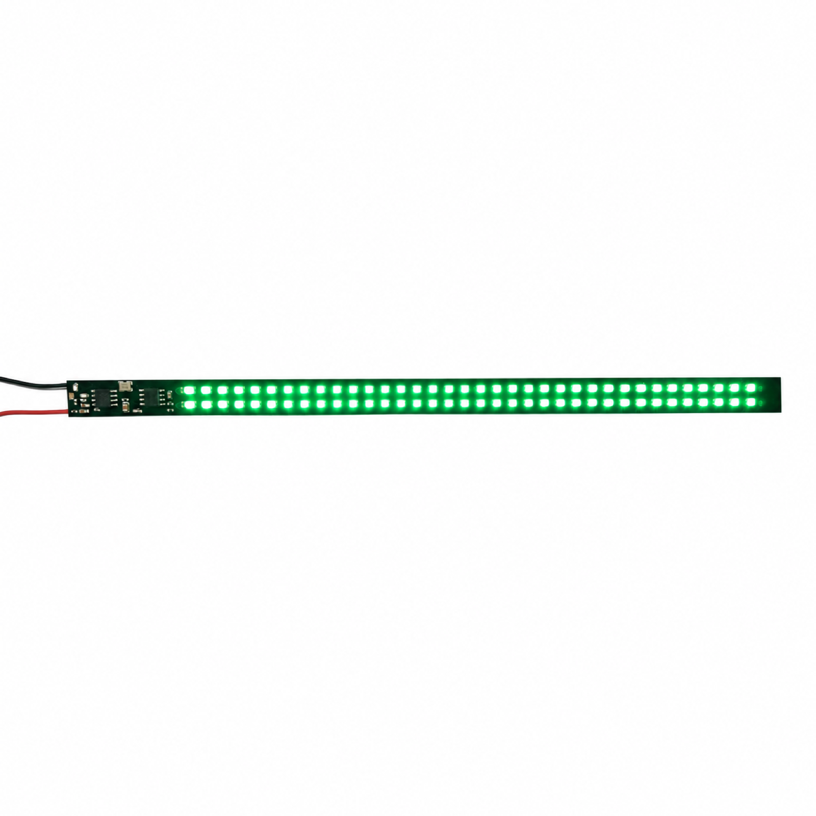
01 / NORMAL RIDING
Green illumination for the normal riding mode. Shown in the supplied product photograph.
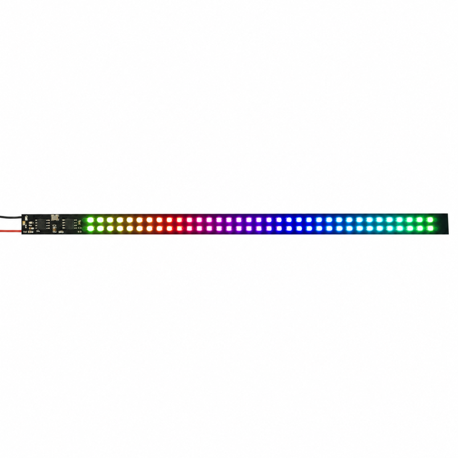
02 / NORMAL RIDING
A colorful alternative to green riding light. This still image shows a multicolor state; see the video for motion.
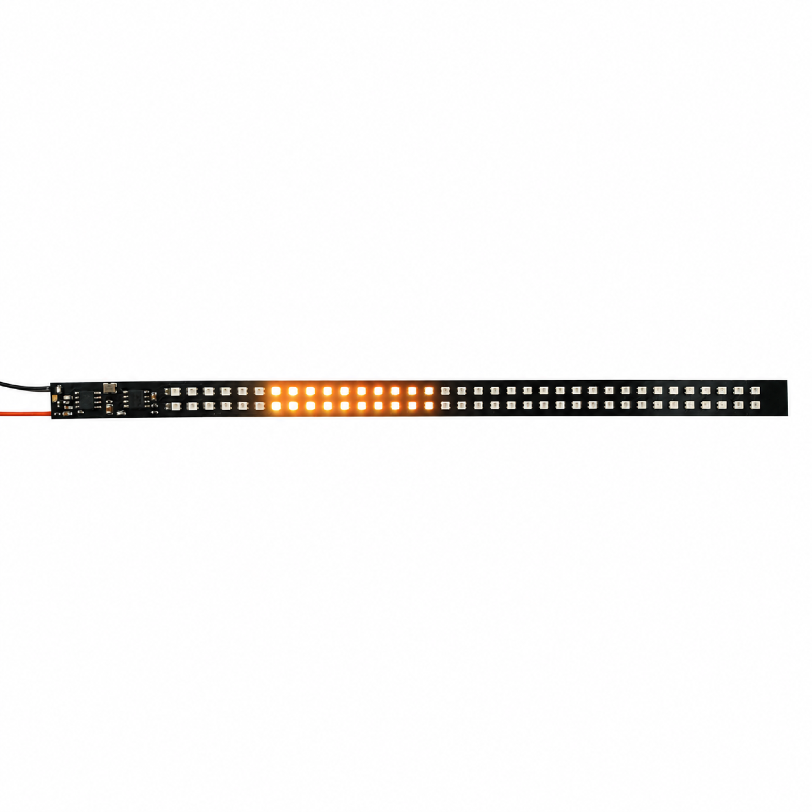
03 / TURN SIGNAL
One captured state of the directional lighting effect. Left-turn and right-turn orientation must be matched to the installed strip.
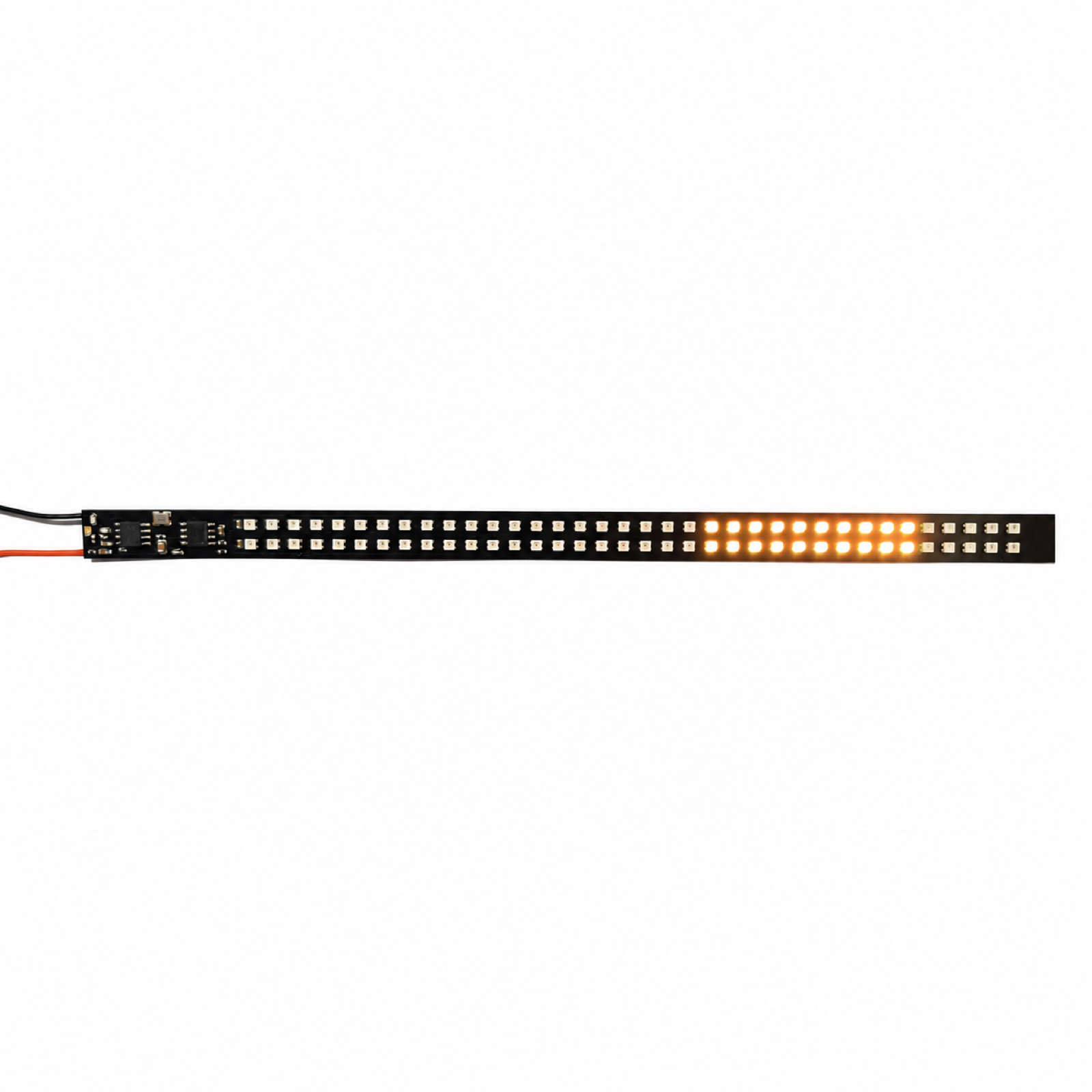
04 / TURN SIGNAL
Another captured state of the directional lighting effect. A still image does not show the direction or full sequence.
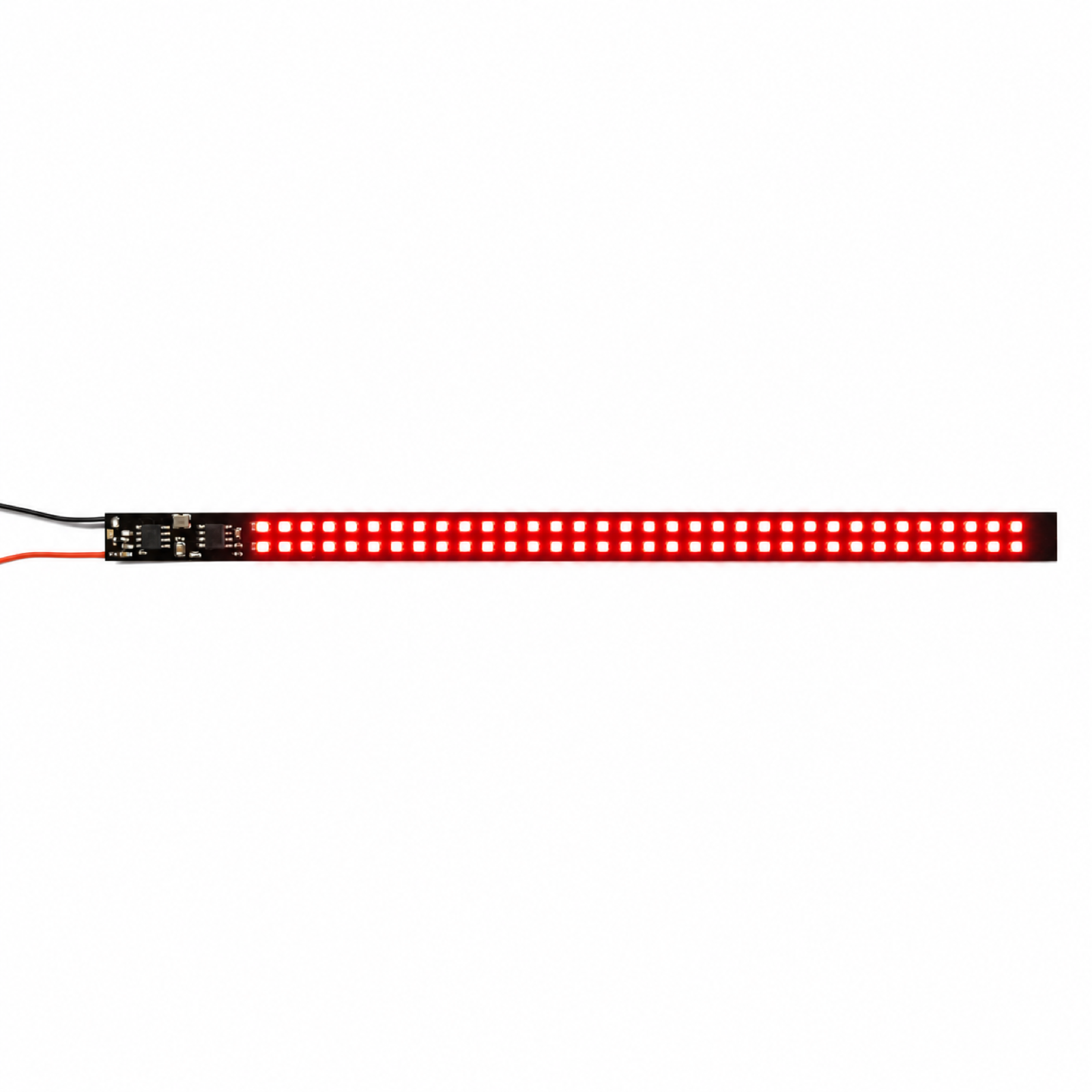
05 / BRAKING
Braking mode uses a rapid red flashing effect. This photograph captures the illuminated state; the brake-trigger method is agreed for the final configuration.
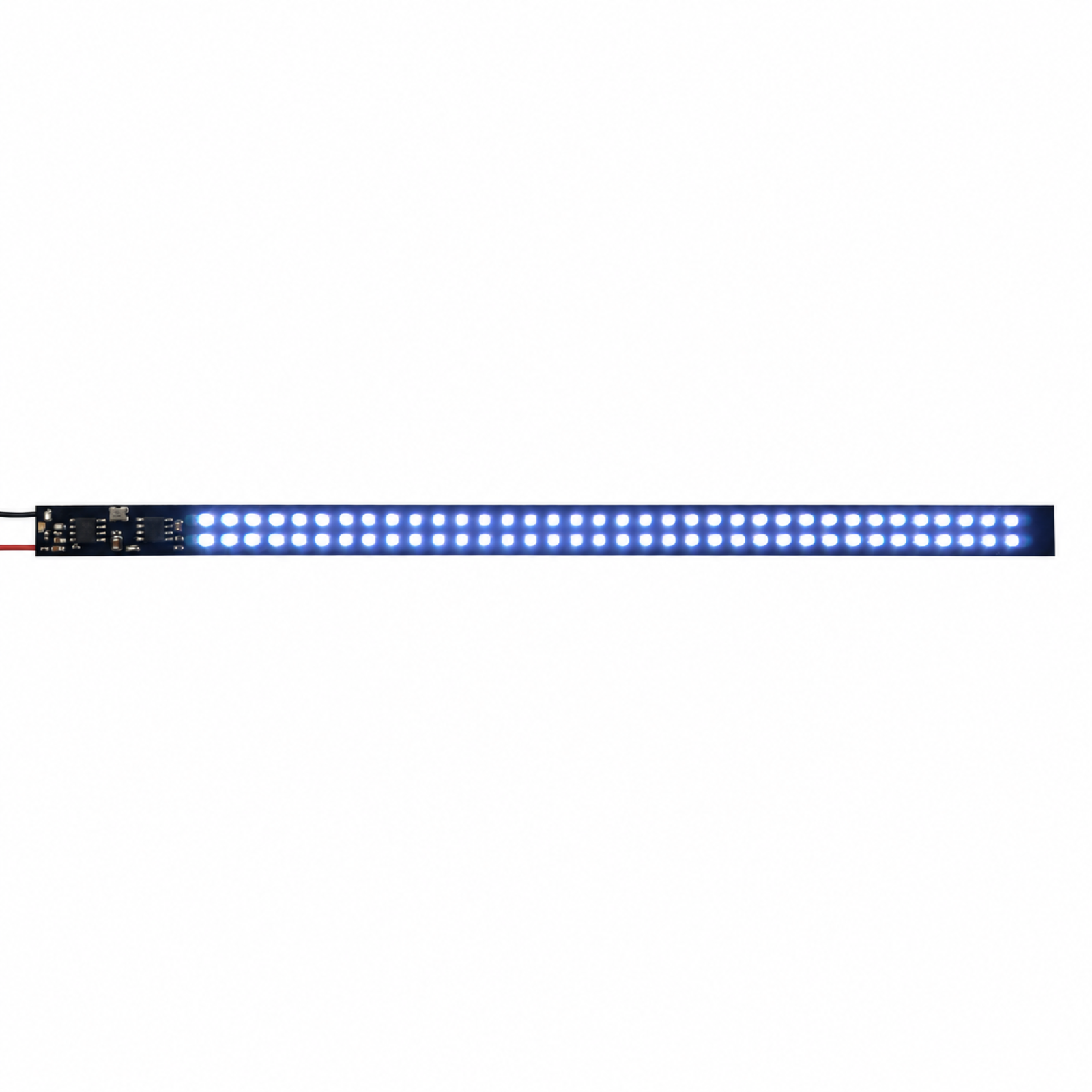
06 / COLOR REFERENCE
Additional supplied color reference. The specified normal riding modes are green or RGB meteor effects.
SUPPLIED DEMONSTRATION VIDEO
The handheld remote is used only to demonstrate effects. Handlebar-mounted button controls can be customized. Flashing-light content: playback is user-initiated, with no autoplay.
PROJECT FIT
Start from the supplied lighting functions, then define the mechanical and control integration.
Position the light strip on the backpack and define a secure mount with accessible power-bank storage.
Customize the rider interface for turn commands and mode selection, with button placement suited to the handlebar.
Agree on the green or meteor riding effect, directional sequences and red brake strobe timing.
Review strip format, wiring, connectors, covers and assembly details for the backpack design.
CONTROLLED DEVELOPMENT PATH
A review result, prototype, or sample remains a project stage. Production begins only from the information and acceptance criteria approved for that project.
Confirm geometry, electrical input, optical target, thermal conditions, quantity, and the available source material.
Define the board, emitter arrangement, drive conditions, connections, mounting, and prototype route.
Review the agreed electrical, optical, thermal, mechanical, and safety-related acceptance points.
Carry the confirmed design, BOM, assembly, inspection, labeling, and packing information into production.
DESIGN & MANUFACTURING SUPPORT
Our in-house PCB design connects your product requirements with manufacturing and testing capabilities at our partner factories.
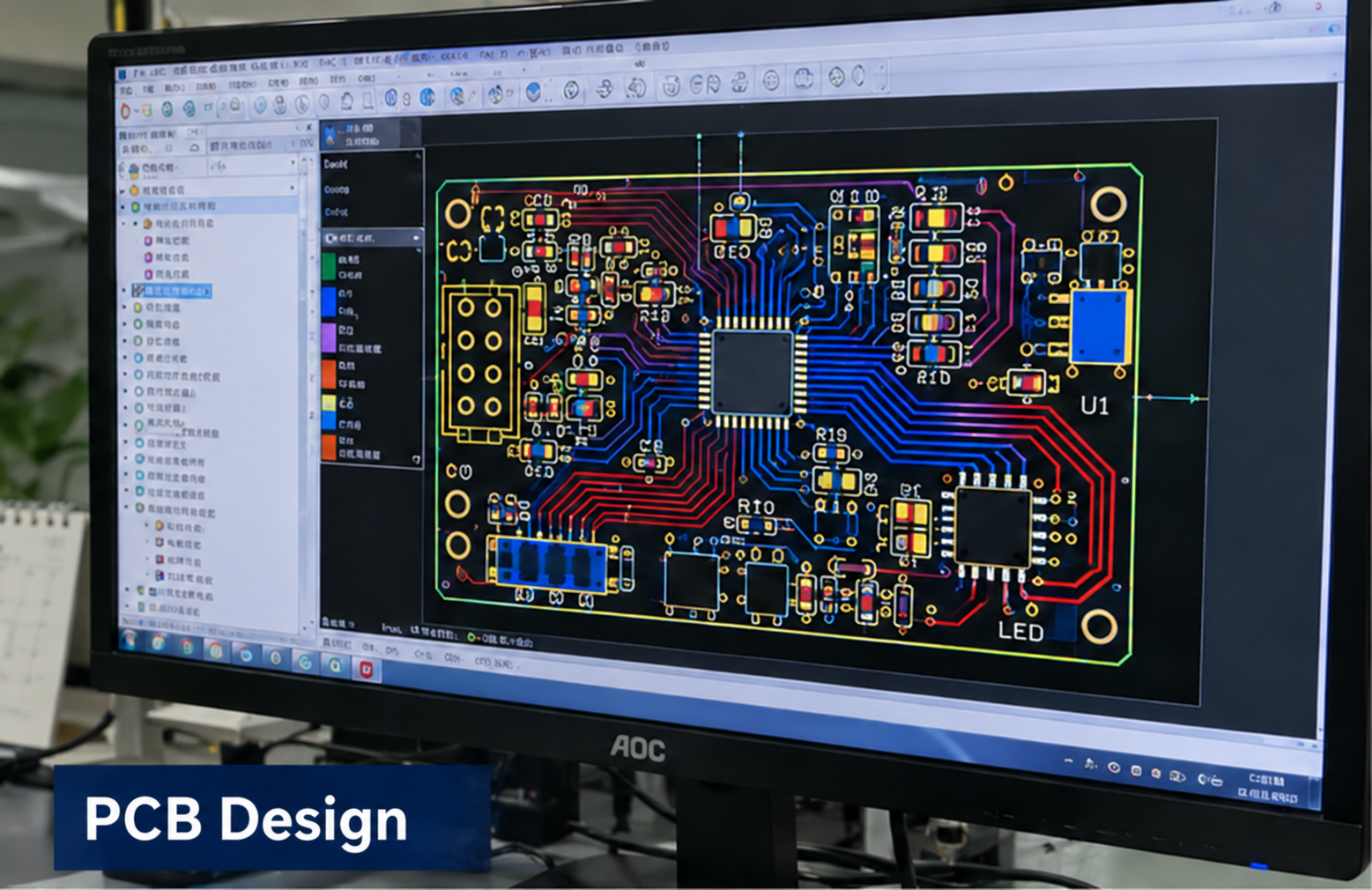
In-house design
Circuit and PCB layout developed around your product requirements.
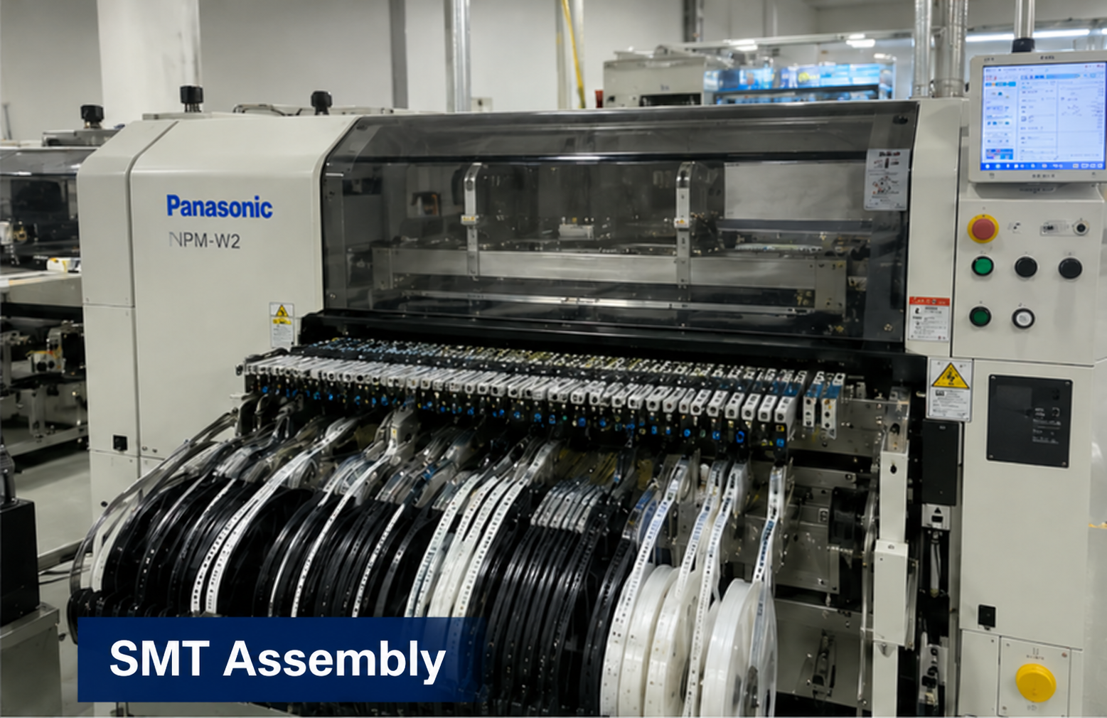
Partner factory
Component placement and assembly for the approved board design.
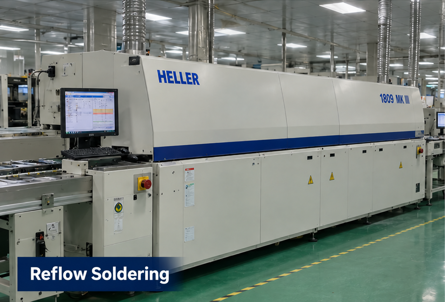
Partner factory
Reflow soldering as part of the board assembly process.
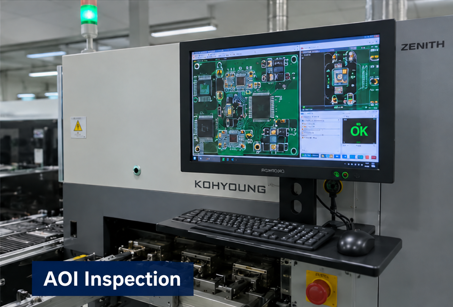
Partner factory
Optical inspection to support assembly quality checks.
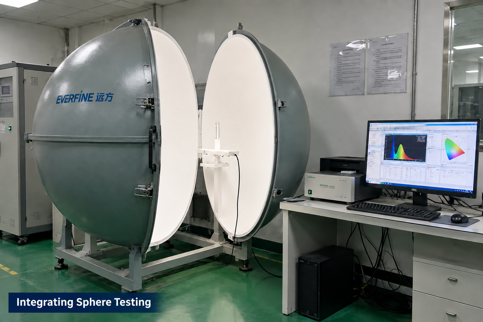
Partner factory
Optical measurement for applicable LED module projects.
Manufacturing and testing scope is agreed for each project. Integrating sphere testing applies to LED optical projects; it is not a required test for every control board. These images illustrate capabilities, not test results or certification for this product.
PROJECT QUESTIONS
These answers describe how a project can begin. They do not promise an unreviewed specification, performance result, certification, schedule, or price.
Send backpack drawings or photos, strip position and orientation, mounting dimensions, 5V power-bank details, cable route, desired riding effects and handlebar-control requirements. Confirm the brake-trigger method and outdoor validation scope separately.
The strip uses a 5V power bank. Confirm the required current, cable and connector for the selected configuration. Runtime depends on the power bank and lighting pattern and is not specified here.
Left turn, right turn and a red strobe braking effect. Normal riding can use green illumination or RGB meteor effects.
No. It is used only for effects demonstration. A handlebar-mounted button remote can be customized.
Automatic brake detection has not been specified. The brake effect and its activation method are separate requirements; confirm the trigger method for the final product.
PROJECT INQUIRY
Include the application, confirmed inputs, preferred targets, expected quantity, target date, and available drawings, photos, files, or samples.
Inquiry about: Cycling Backpack LED Strips