Spectrum & emitter
Target wavelength range, spectral distribution, LED package, bin, optical output data, operating point, supplier information, and traceability.
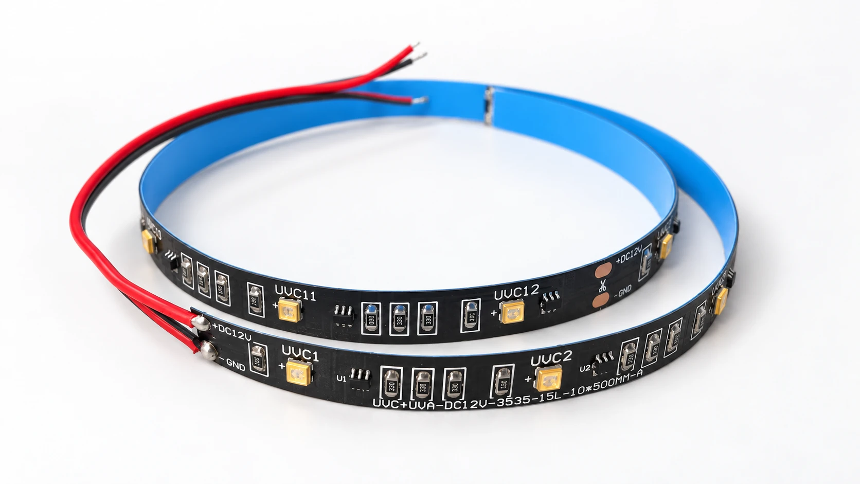
FLEXIBLE UVC LIGHT SOURCE DEVELOPMENT
Develop a flexible UVC LED strip for enclosed OEM equipment. Share the required spectrum, installation path, drive conditions and thermal arrangement, then confirm the exact strip version, cut intervals and system validation requirements.
Switch this illustration on or off. No physical device is connected.
Illustration OFF · Physical hardware is not connected.
This diagram does not show actual irradiance, dose, wavelength, LED placement or disinfection performance. Confirm the selected product and validate the complete system. Disconnect power before access or servicing.
UV safety information — FDA ↗Reference media shows version-specific 12V, 12–15V, and 24V markings
Flexible geometry, segment layout, wiring, and mounting reviewed together
Spectrum, dose, and disinfection claims require measured validation
Review the inputs needed to start
↓APPLICATION FIRST
A strip can distribute emitters along a compact path, but delivered UVC dose still depends on measured spectrum and optical output, distance, angle, exposure time, airflow or water path, shadowing, fouling, temperature, aging, and chamber geometry. The strip must be enclosed and evaluated inside the intended equipment.
UVC SAFETY
Avoid direct eye and skin exposure. Final equipment should use enclosure, shielding, access control or interlocks, status indication, and controlled service procedures appropriate to the application.
DEFINE BEFORE DESIGN
Confirmed requirements, preferred targets, and open questions can all be included in the first brief. Unknown values stay visible until they are reviewed.
Target wavelength range, spectral distribution, LED package, bin, optical output data, operating point, supplier information, and traceability.
Overall dimensions, LED pitch, approved cut interval, bend limits, copper pads, reconnection method, mounting surface, and available installation space.
Rated voltage and current, polarity, load per segment, maximum feed length, voltage drop, current control, switching or dimming, protection, and fault behavior.
Flexible-board construction, chassis or heat-spreader contact, interface material, ambient or fluid temperature, duty cycle, and allowable component temperature.
Backing or adhesive requirement, cable materials, nearby plastics and seals, moisture, condensation, cleaning chemicals, coatings, and any required ingress test.
Enclosure, shielding, access interlock, status indication, sensors, irradiance or dose measurement, aging, microbiological test method, and acceptance criteria.
REFERENCE MEDIA
The supplied media shows different circuit layouts, reel labels, and voltage markings. They are presented as version-specific reference evidence rather than one fixed production specification.
REFERENCE LAYOUT A
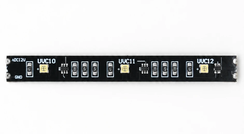
The supplied source sample is marked “UVC+UVA-DC12V-3535-15L-10*500MM-A”. Its wavelength, output, dimensions, LED count, and approved electrical limits still require a controlled specification.
REFERENCE LAYOUT B
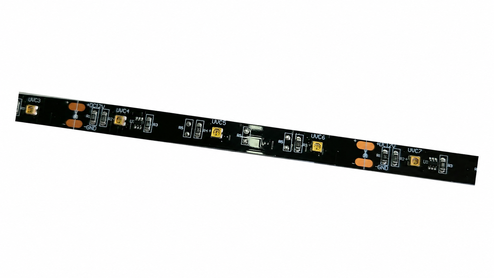
This second layout shows scissor marks, copper connection pads, three LED positions between adjacent cut lines, and several unpopulated pads. Its approved cut length, load, and optional functions require confirmation for the exact version.
REEL LABEL REFERENCE
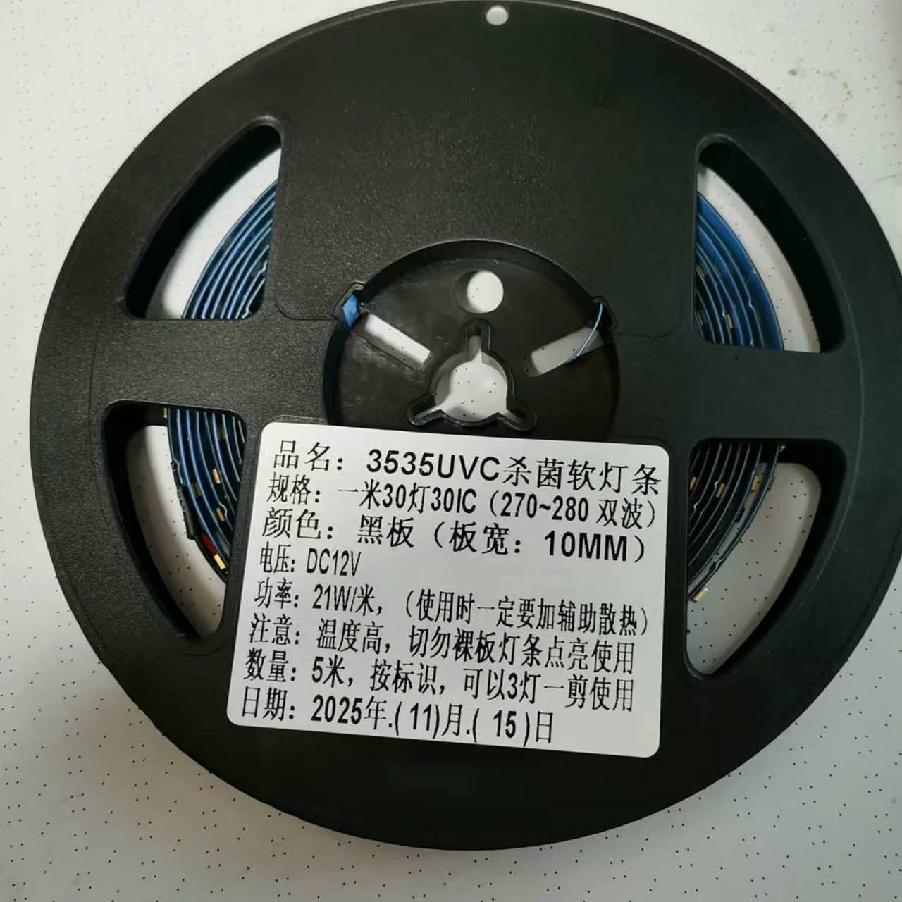
One reel label lists 30 LEDs and 30 ICs per meter, “270–280 dual wavelength” (label wording), a 10 mm board width, DC 12V, and 21 W/m. The same label requires auxiliary heat dissipation, says not to power the bare strip, and permits cutting every three LEDs at the marked points. These are batch-reference label values; measured spectrum and the approved production specification still require confirmation.
BATCH REFERENCE
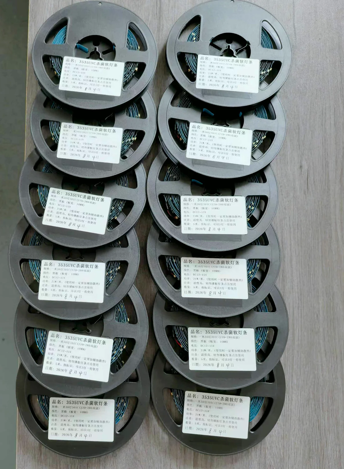
The photographed reel labels show a later batch marked DC 12–15V. Reel quantity, electrical limits, spectrum, output, and acceptance records must follow the approved order and batch documentation rather than a different sample photo.
PACKING REFERENCE
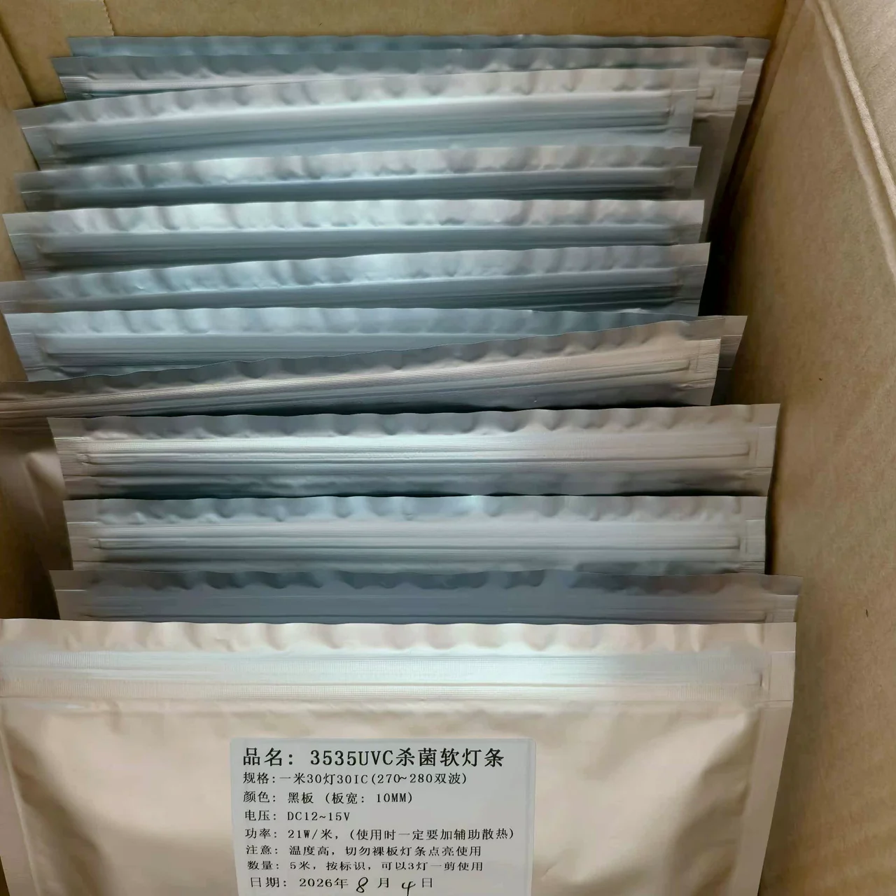
This photograph records the supplied packing format only. Barrier-bag material, moisture protection, electrostatic controls, labeling, carton quantity, and shipping validation remain order-specific requirements.
VOLTAGE-VARIANT REFERENCE
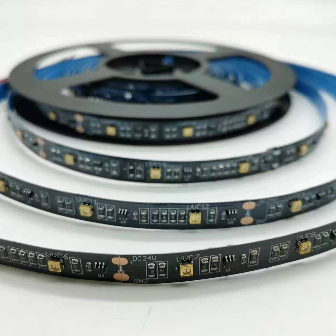
A separate supplied close-up is visibly marked DC 24V, while reel labels in other photos show DC 12V or DC 12–15V. This confirms that voltage, circuit layout, feed length, current, and power must be selected and documented by exact version.
UNPOWERED CONSTRUCTION REFERENCE
This silent clip documents the physical sample only. It does not demonstrate operating spectrum, radiant output, dose, heat performance, waterproofing, or disinfection results.
PROJECT FIT
Application suitability remains conditional until the selected emitter, complete enclosure, operating conditions, and validation method are confirmed.
Emitter spacing, airflow, residence time, shadowing, chamber reflectance, thermal path, containment, sensing, and maintenance access.
Working distance, uniformity, timing, target coverage, shielding, access control, indicators, and application-level test criteria.
Flexible routing, bend limits, voltage drop, mounting, heat transfer, nearby material exposure, wiring, and service procedure.
Compare layout, drive, optical distribution, temperature, safety controls, aging, and measurable acceptance points before production.
CONTROLLED DEVELOPMENT PATH
A review result, prototype, or sample remains a project stage. Production begins only from the information and acceptance criteria approved for that project.
Confirm geometry, electrical input, optical target, thermal conditions, quantity, and the available source material.
Define the board, emitter arrangement, drive conditions, connections, mounting, and prototype route.
Review the agreed electrical, optical, thermal, mechanical, and safety-related acceptance points.
Carry the confirmed design, BOM, assembly, inspection, labeling, and packing information into production.
DESIGN & MANUFACTURING SUPPORT
Our in-house PCB design connects your product requirements with manufacturing and testing capabilities at our partner factories.
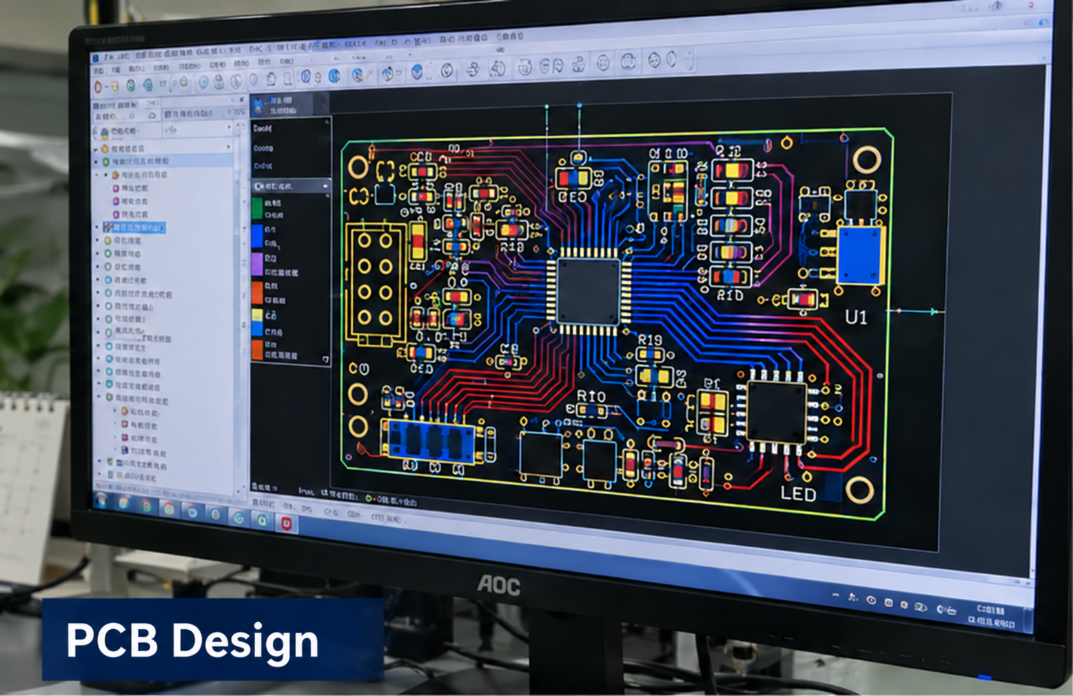
In-house design
Circuit and PCB layout developed around your product requirements.
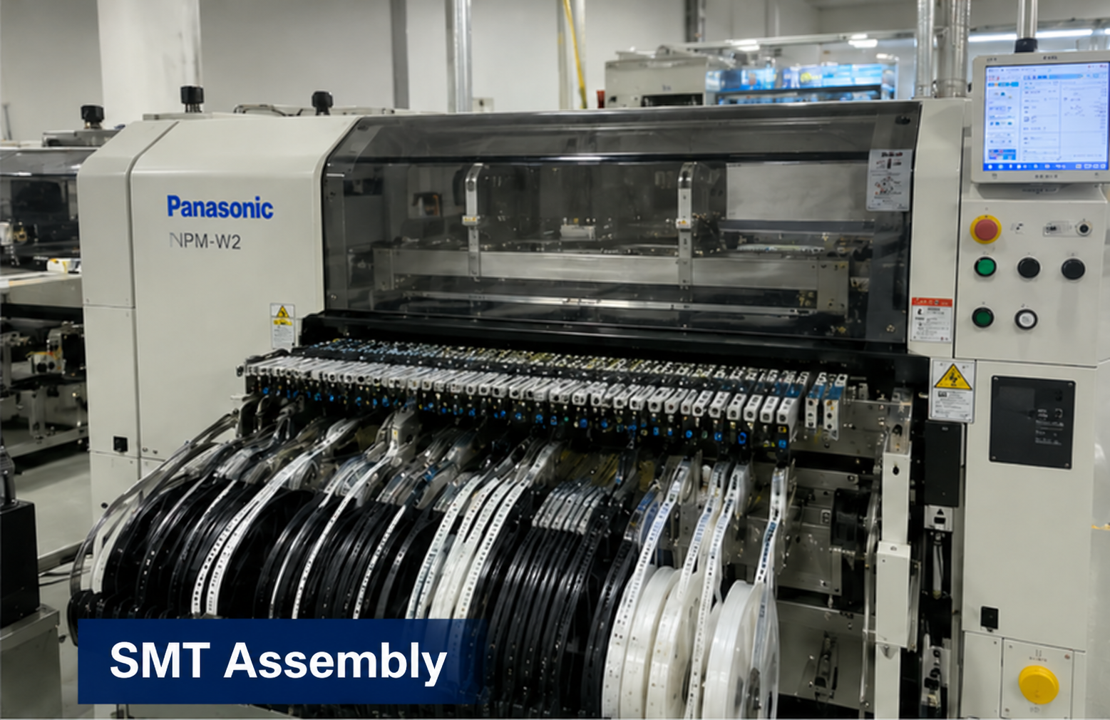
Partner factory
Component placement and assembly for the approved board design.
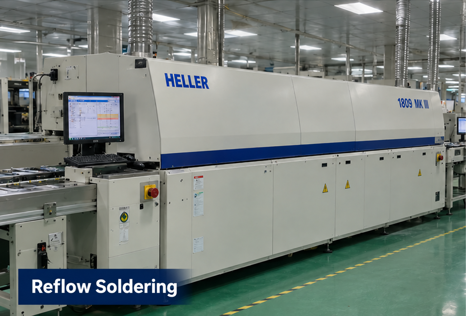
Partner factory
Reflow soldering as part of the board assembly process.
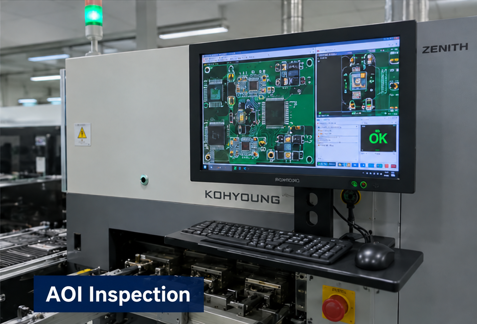
Partner factory
Optical inspection to support assembly quality checks.
Partner factory
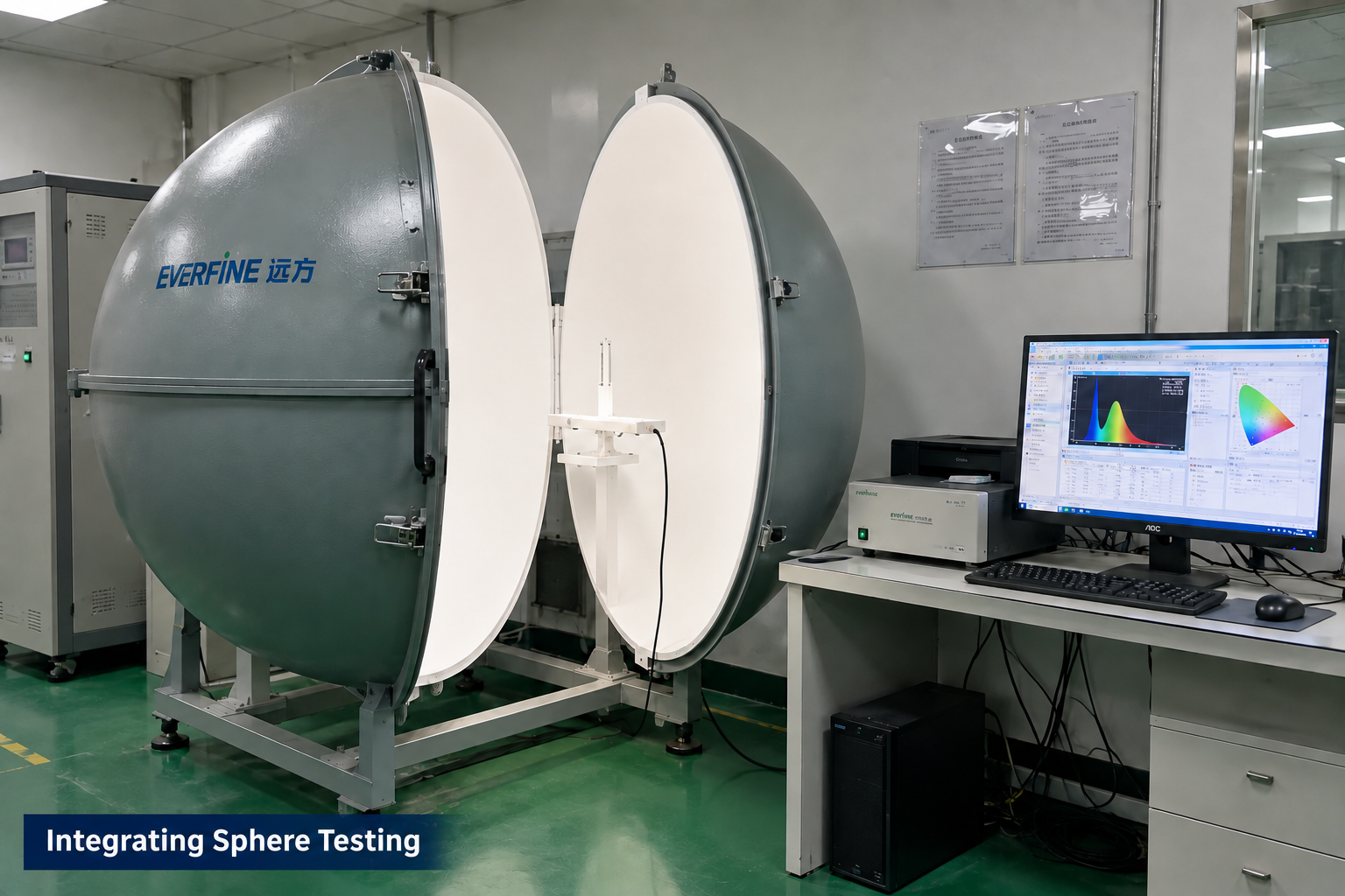
Optical measurement for applicable LED module projects.
Manufacturing and testing scope is agreed for each project. Integrating sphere testing applies to LED optical projects; it is not a required test for every control board. These images illustrate capabilities, not test results or certification for this product.
PROJECT QUESTIONS
These answers describe how a project can begin. They do not promise an unreviewed specification, performance result, certification, schedule, or price.
Send the equipment application, required spectrum, installation dimensions, selected sample or version, electrical drive, mounting and heat path, enclosure, cut and connection needs, quantity and validation plan. Reference-label values must be checked against the exact ordered version.
No. The strip alone does not establish delivered dose or microbiological result. Spectrum, optical output, geometry, exposure time, target organism, operating conditions, aging, and the complete system must be tested.
No waterproof or IP claim can be made from the supplied media. Exposed components are visible. Any coating, sleeve, enclosure, immersion condition, and ingress test must be confirmed separately.
The supplied media shows different references: one reel label states DC 12V, later reel labels show DC 12–15V, and a separate strip photograph is marked DC 24V. Voltage, tolerance, current, polarity protection, feed length, and power must therefore be confirmed for the exact ordered version.
One reference layout shows scissor marks and copper pads, with three LED positions between adjacent cut lines. The approved cut interval and reconnection method must be confirmed for the exact production version because another supplied sample uses a different layout.
RECOMMENDED READING
For linear UVC installations, review exposure along the strip and nearby plastic parts. This case explains distance, cumulative dose, shielding and material validation.
Read the UVC safety articlePROJECT INQUIRY
Include the application, confirmed inputs, preferred targets, expected quantity, target date, and available drawings, photos, files, or samples.
Inquiry about: UVC LED Strips