
Battery system
Chemistry, cell count, capacity, pack limits, protection board, balancing need, connector, and available pack data.
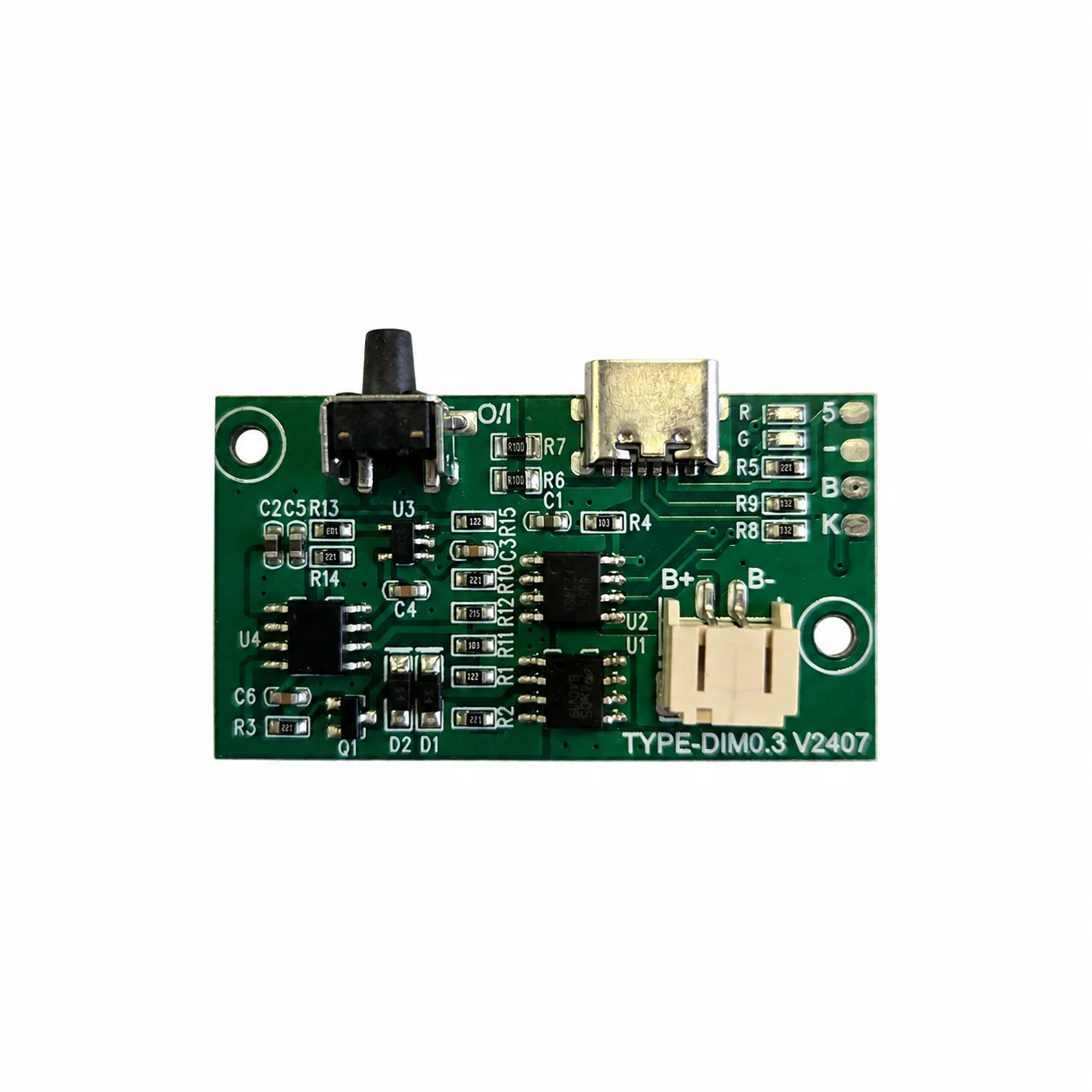
RECHARGEABLE LED LIGHTING · THREE-LEVEL DIMMING
Power rechargeable LED lighting with a battery-box controller. Press and hold to turn power on or off; short press to cycle brightness: 30% → 60% → 100% → 30%. The Type-C port accepts 5V for charging and provides 3.7–4.2V in output mode for the intended lighting load. Not for use as a power bank.
Press and hold to turn the light on or off. Short press to cycle 30% → 60% → 100%.
When on, tap to cycle 30% → 60% → 100% → 30%. Hold to switch power; releasing after a hold does not change the brightness level.
Keyboard: Enter or Space to tap / hold. When off, hold to turn the light back on.
Lighting illustration only, not measured light output. The demo starts at 100%; one short press selects 30%. Hold timing and the restart brightness of the actual product are confirmed for the selected configuration.
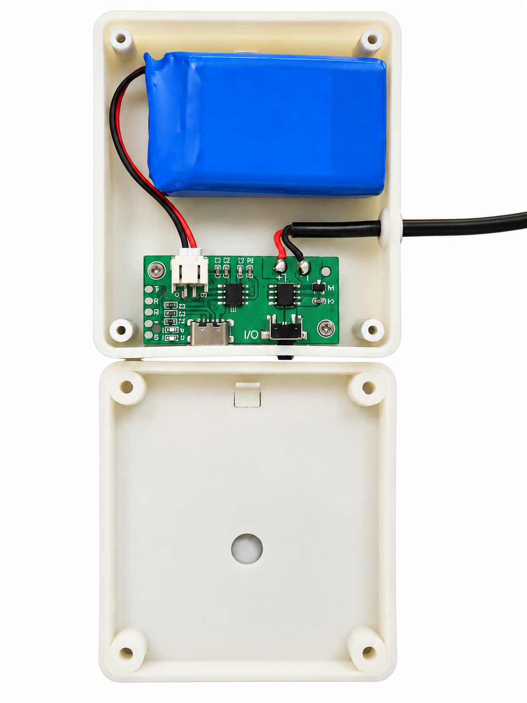
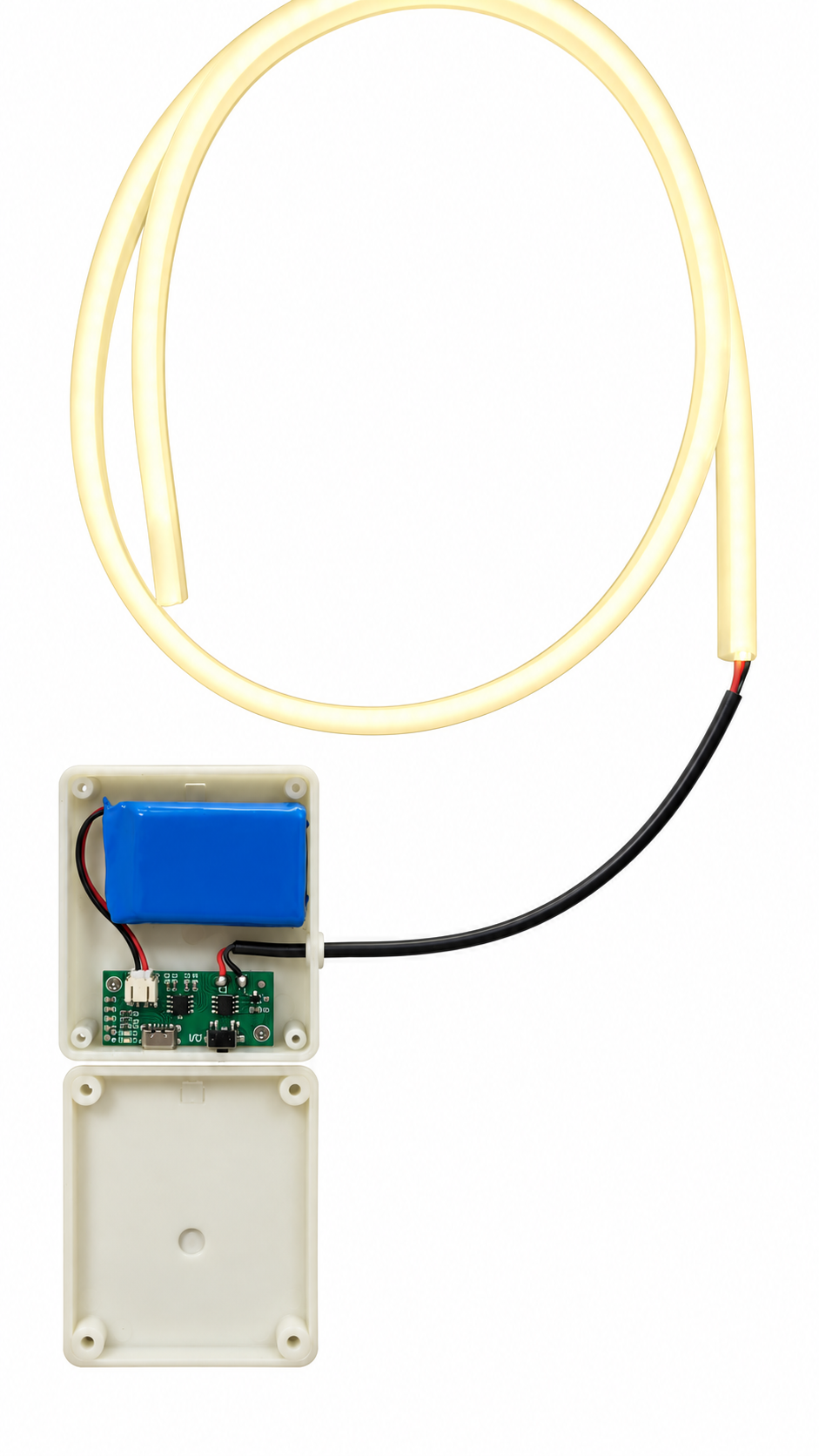
View the battery box & lighting assemblyPress and hold: power on / off
Short press: 30% → 60% → 100% → 30%
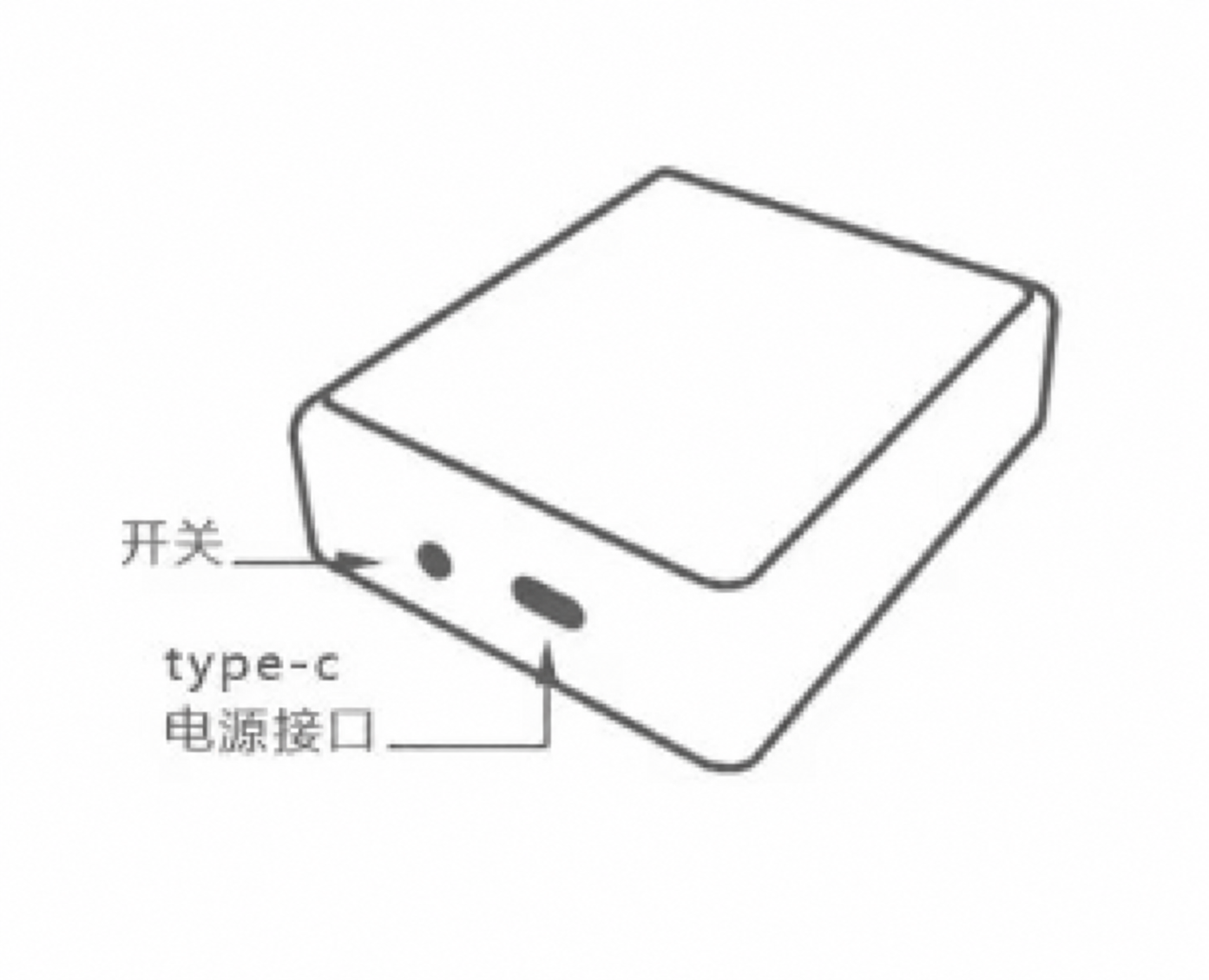
Type-C: 5V charging input · 3.7–4.2V output
Review the inputs needed to start
↓APPLICATION FIRST
The battery-box example combines a rechargeable battery, charging and dimming board, and a connected LED light strip. It can be reviewed for portable illuminated products such as the supplied bag application. Match the lighting load, battery and enclosure to the selected configuration.
IMPORTANT CONNECTION WARNING
Do not connect this battery box to other rechargeable devices. Do not use it to charge phones, tablets, power banks or other rechargeable equipment. The Type-C output is 3.7–4.2V for the intended lighting load, not a general-purpose 5V USB charging output.
BATTERY-POWERED LIGHTING
Assembly views and an illuminated product application. The two assembly photographs have been edited to a white background; the bag photograph is supplied application material, not a runtime or brightness test.

SWITCH & TYPE-C PORT
Hold duration, battery capacity, charging time and current ratings are not specified. Confirm these details for the selected configuration.
DEFINE BEFORE DESIGN
Confirmed requirements, preferred targets, and open questions can all be included in the first brief. Unknown values stay visible until they are reviewed.
Chemistry, cell count, capacity, pack limits, protection board, balancing need, connector, and available pack data.
Supply type, voltage range, connector, available power, negotiation requirements, polarity, and transient conditions.
Target current and voltage, pre-charge, termination, recharge behavior, timing, and any cell-maker limits.
Charge-only or charge-while-operating behavior, load sharing, cutoff states, standby current, and power sequencing.
Temperature sensing, current and voltage limits, reverse conditions, short-circuit behavior, heat path, and enclosure.
Indicators, buttons, host communication, logging, acceptance criteria, test method, and applicable compliance review.
PROJECT FIT
A useful first review separates confirmed battery limits from desired product behavior and unresolved compliance questions.
Coordinate the pack, input, charging, load, indicators, enclosure, and thermal path.
Review the actual power requirement and negotiation scope before changing the connector or source.
Address form factor, heat, indicators, standby behavior, connectors, or component availability.
Define status signals, control commands, fault reporting, and power-state ownership.
CONTROLLED DEVELOPMENT PATH
A review result, prototype, or sample remains a project stage. Production begins only from the information and acceptance criteria approved for that project.
Confirm the application, functions, electrical limits, interfaces, mechanical constraints, quantity, and open questions.
Develop the agreed circuit, PCB layout, firmware scope, connectors, and prototype route.
Check the agreed functional, electrical, thermal, communication, and fit criteria, then record revisions.
Release only the approved design, component, firmware, assembly, inspection, and packing information.
DESIGN & MANUFACTURING SUPPORT
Our in-house PCB design connects your product requirements with manufacturing and testing capabilities at our partner factories.
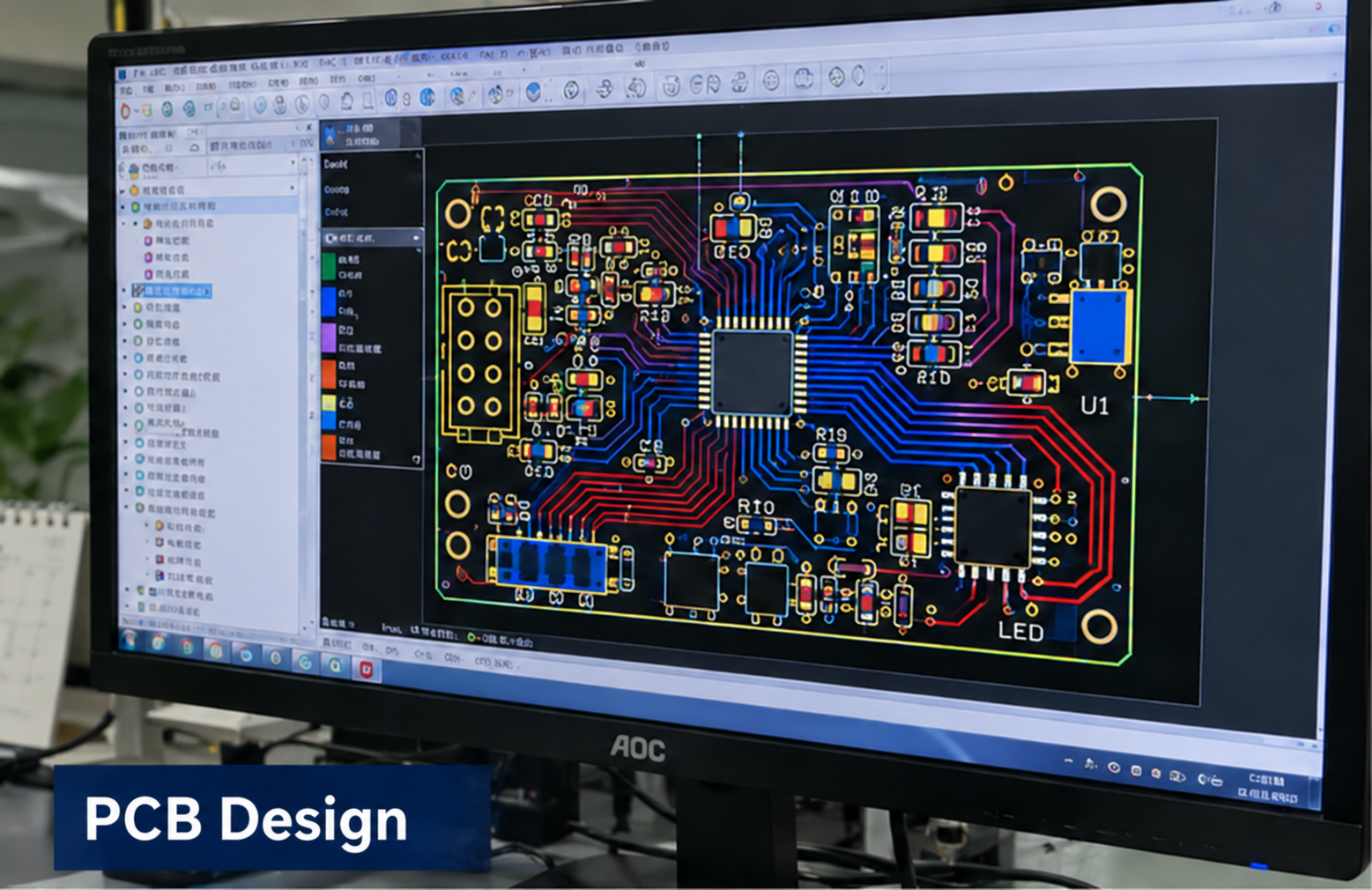
In-house design
Circuit and PCB layout developed around your product requirements.
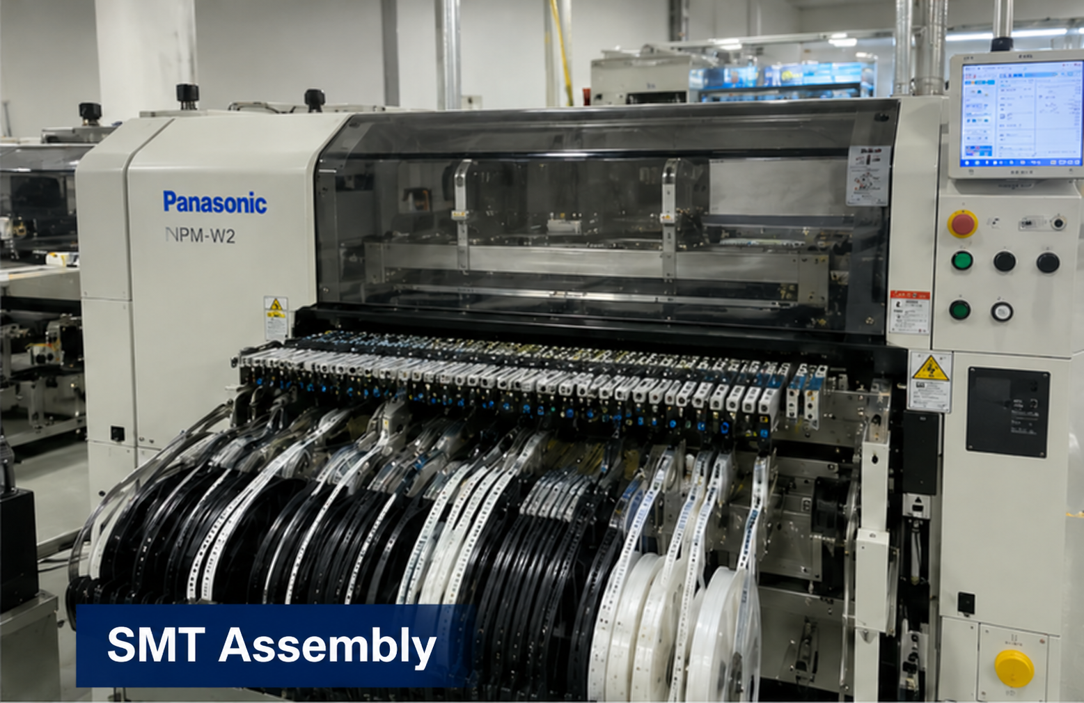
Partner factory
Component placement and assembly for the approved board design.
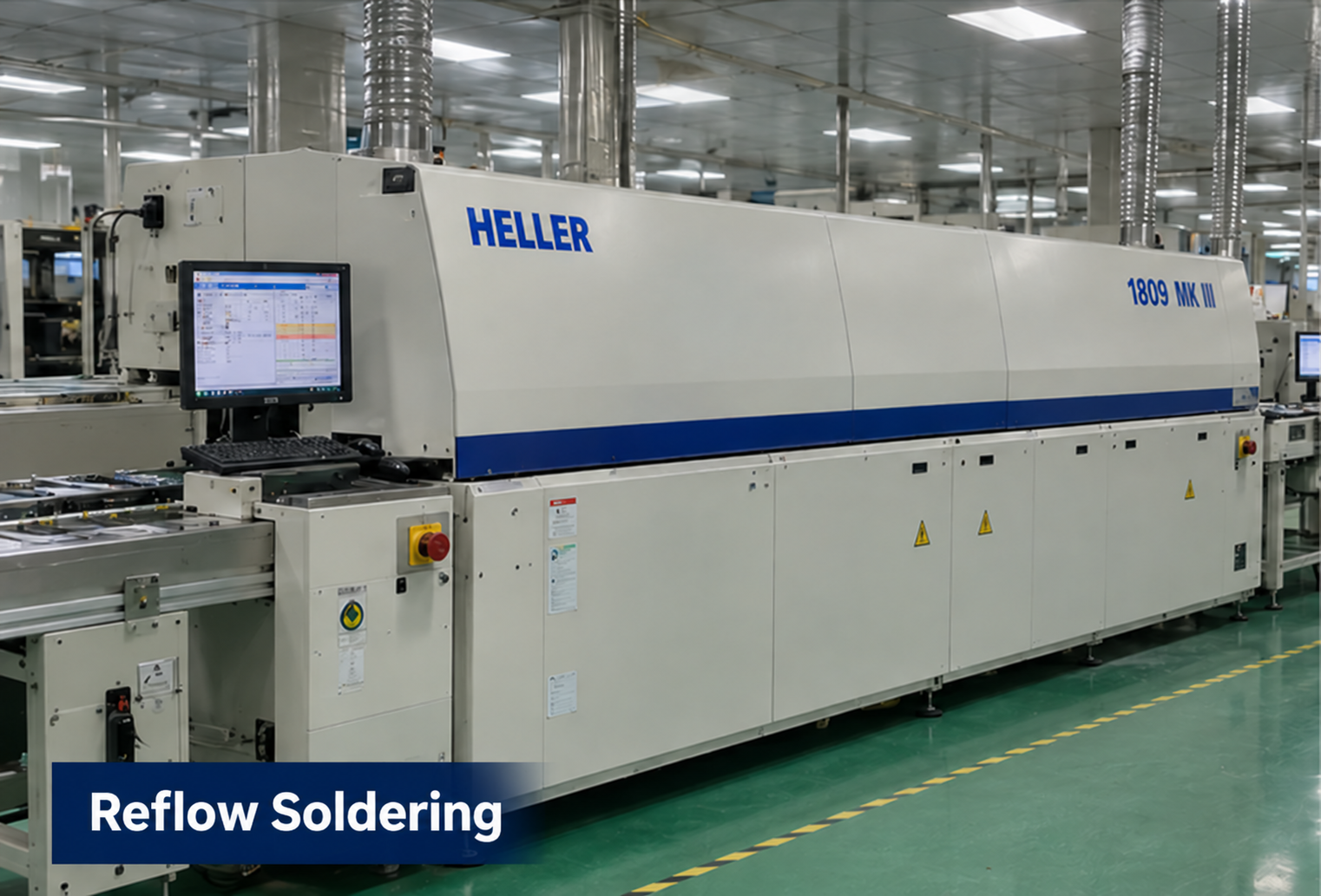
Partner factory
Reflow soldering as part of the board assembly process.
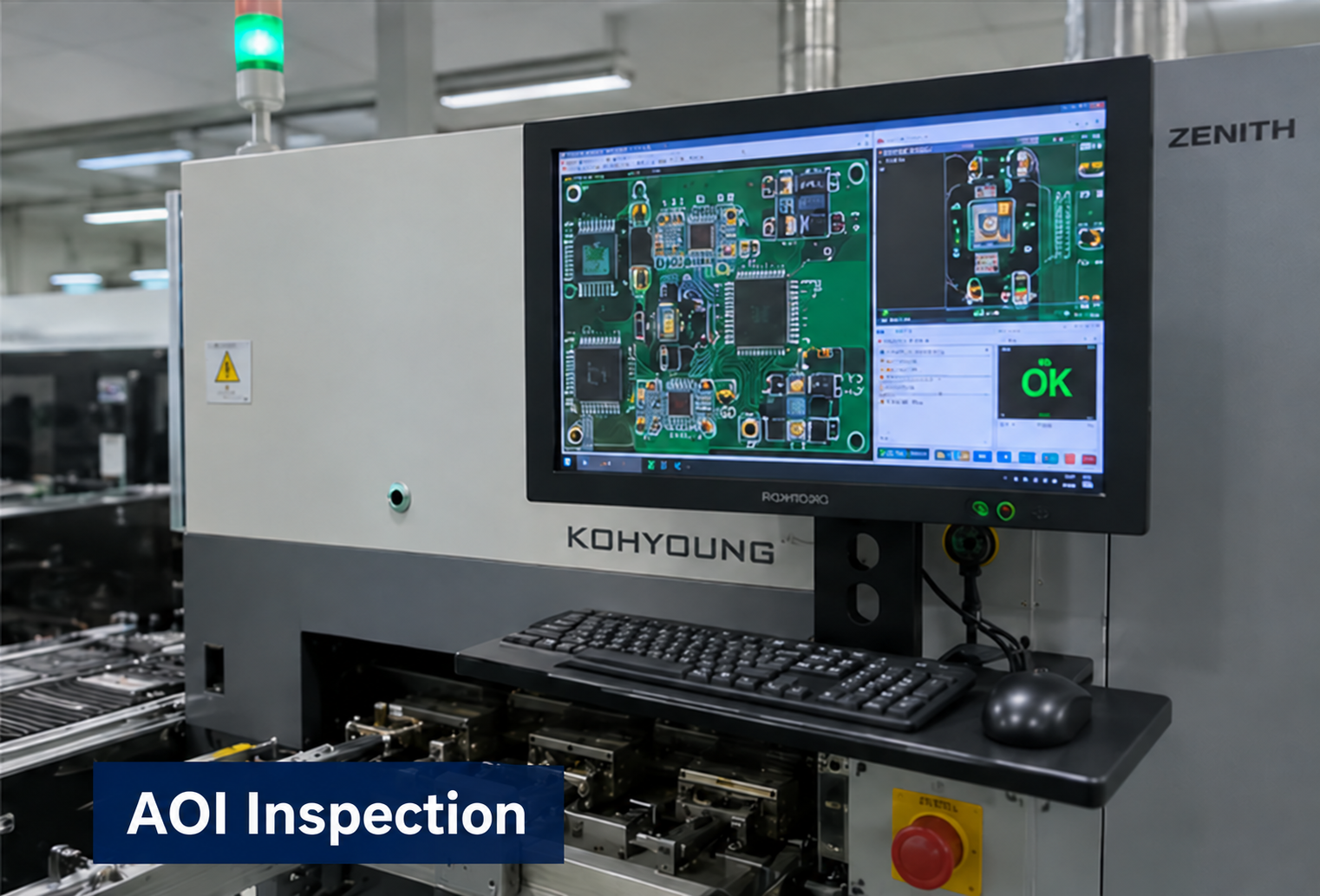
Partner factory
Optical inspection to support assembly quality checks.
Partner factory
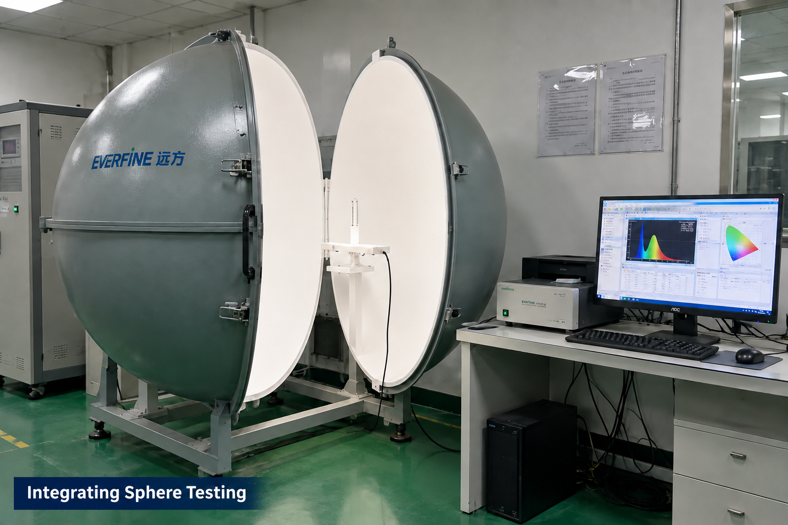
Optical measurement for applicable LED module projects.
Manufacturing and testing scope is agreed for each project. Integrating sphere testing applies to LED optical projects; it is not a required test for every control board. These images illustrate capabilities, not test results or certification for this product.
PROJECT QUESTIONS
These answers describe how a project can begin. They do not promise an unreviewed specification, performance result, certification, schedule, or price.
Press and hold the battery-box switch to turn power on or off. The required hold duration is not specified.
Short press the battery-box switch to cycle through three brightness levels in this order: 30% → 60% → 100% → 30%. Press and hold to turn power on or off.
Charging input is 5V. In output mode, the specified voltage is 3.7–4.2V. Confirm the intended lighting load and cable arrangement before connection.
No. Connecting the battery box to other rechargeable devices is prohibited. It must not be used to charge phones or other rechargeable equipment.
No. Connector shape does not establish the negotiated voltage, current, protocol, cable requirement, or available power. Those functions must be specified and verified.
It may be possible, but the load profile, input capacity, power-path architecture, battery limits, heat, fault behavior, and user expectations must be reviewed.
Protection may be on the cell pack, the charging board, or both. The responsibility and limits of each protection layer must be defined before design approval.
Provide battery chemistry, cell count, capacity, voltage limits, permitted charge current, pack datasheet, protection details, connector, temperature sensor, LED load and target operating conditions. Confirm the enclosure and requested dimming behavior for the selected configuration.
PROJECT INQUIRY
Include the application, confirmed inputs, preferred targets, expected quantity, target date, and available drawings, photos, files, or samples.
Inquiry about: Charging Control Boards