
Treatment objective
Target organism or water-quality objective, required reduction, operating mode, and static or flowing water.
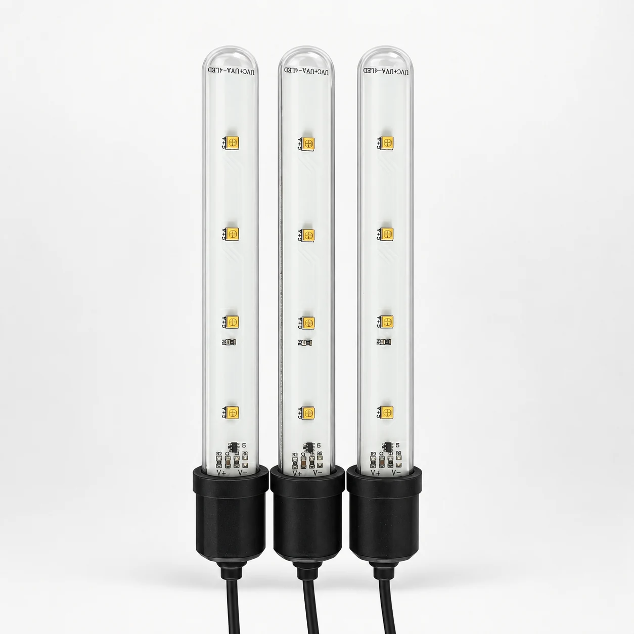
24V UVA + UVC · WATERPROOF LAMP
A dual-sided UVA + UVC LED lamp with an aluminum PCB and quartz-glass tube for enclosed water-system integration. Reference input: DC 24V / 120mA; typical total UVC radiant power: 60mW. Application performance requires complete-system validation.
Switch this illustration on or off. No physical device is connected.
Illustration OFF · Physical hardware is not connected.
This diagram does not show actual irradiance, dose, wavelength, LED placement or disinfection performance. Confirm the selected product and validate the complete system. Disconnect power before access or servicing.
Front-side illustration only. A waterproof tube does not provide UV shielding for people.
UV safety information — FDA ↗DC 24V / 120mA · nominal 3W
270–280nm UVC · 395–405nm UVA
Dual-sided construction · 60mW typical UVC
Review the inputs needed to start
↓APPLICATION FIRST
Water ingress resistance does not establish the required UVC dose throughout a tank or flow path. Flow, exposure time, water transmittance, distance, shadowing, fouling, aging and chamber geometry affect what reaches the target. Electrical wattage or nominal radiant power must not be converted directly into a sterilization percentage.
WARNING — UVC RADIATION
Never look directly at an operating UVC source or expose eyes or skin. Quartz transmits UVC and is not a protective shield. Use an opaque, interlocked enclosure and disconnect power before inspection or service. Prevent direct exposure to fish, plants and sensitive materials.
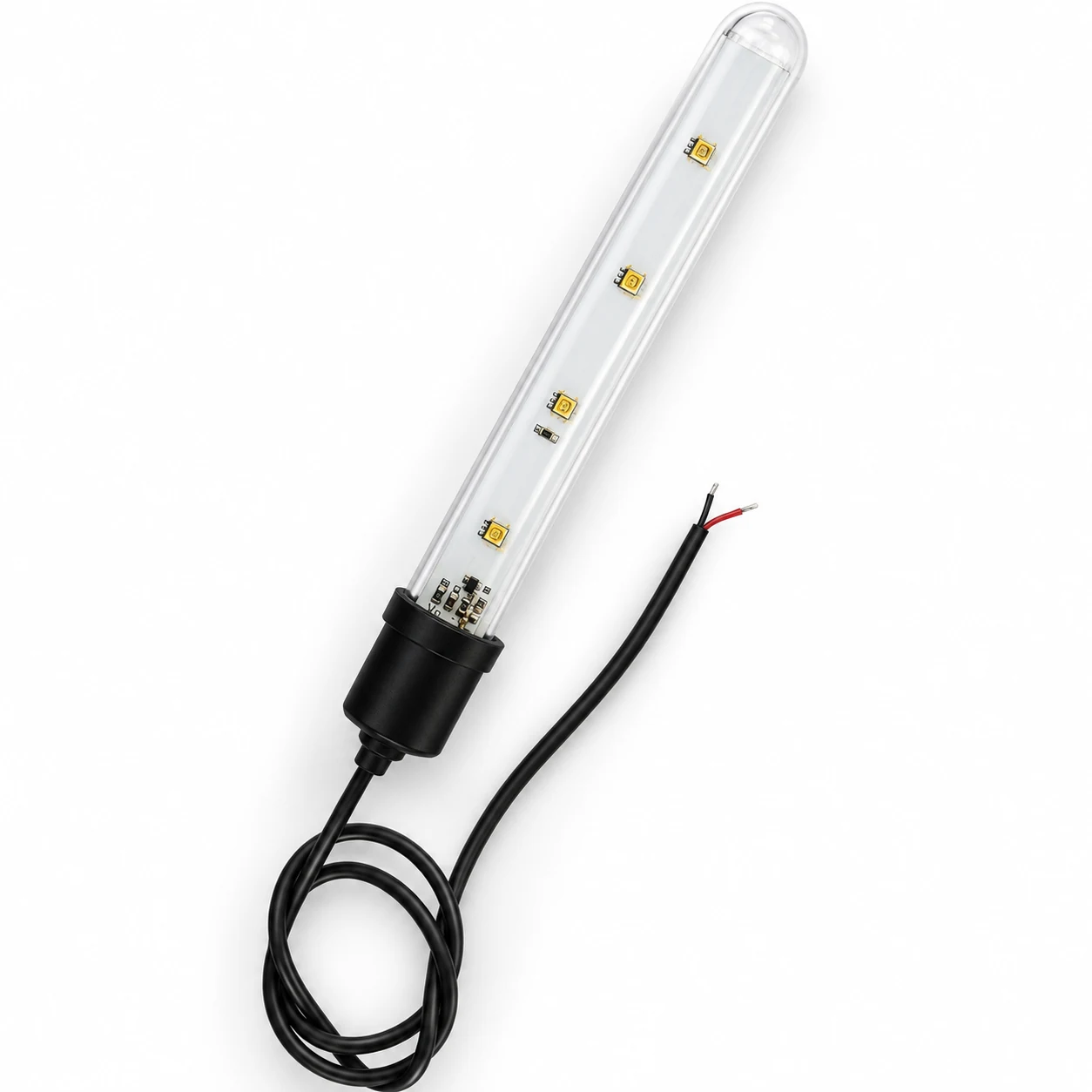
REFERENCE CONFIGURATION
The reference module uses a linear aluminum PCB inside a quartz-glass tube, with four dual-wavelength 3535 UVA + UVC LED packages on each side.
* Confirm dimension definition, immersion test conditions, and temperature definition in the approved project specification.
DEFINE BEFORE DESIGN
Confirmed requirements, preferred targets, and open questions can all be included in the first brief. Unknown values stay visible until they are reviewed.
Target organism or water-quality objective, required reduction, operating mode, and static or flowing water.
Tank or chamber dimensions, water depth, lamp position, distance, reflection, shadowing, and water-level variation.
Flow or mixing, UV transmittance, turbidity, temperature, fouling, chemistry, and maintenance interval.
Plastics, seals, adhesives, cables, coatings, sensors, windows, and their long-term UVC compatibility.
Supply tolerance, polarity, switching, duty cycle, faults, ambient or water temperature, and heat path.
Shielding, interlocks, level or flow sensing, fault indication, optical measurement, aging, and microbiological tests.
REFERENCE MEDIA
Supplied photographs and video show construction, not dose, waterproofing, lifetime or system-performance test results.
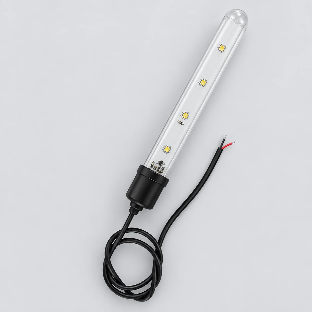
PRODUCT CONSTRUCTION
Confirm dimensions, cable entry, strain relief and installation conditions for the selected module.
REAL MODULE VIEW
Shows five lamps, quartz tubes, cable entries, end caps and dual-sided linear PCBs. Never power an exposed UVC source for direct viewing.
PROJECT FIT
Keep the active UVC zone enclosed. Validate water conditions, exposed materials, flow, temperature and maintenance for the selected layout.
Place the lamp in a closed filter or circulation chamber, away from livestock and user access.
Use an internal baffle so water circulates through the treatment area without exposing the complete tank.
Move treatment into an enclosed UVC-compatible chamber for clearer geometry, servicing, and validation.
CONTROLLED DEVELOPMENT PATH
A review result, prototype, or sample remains a project stage. Production begins only from the information and acceptance criteria approved for that project.
Confirm geometry, electrical input, optical target, thermal conditions, quantity, and the available source material.
Define the board, emitter arrangement, drive conditions, connections, mounting, and prototype route.
Review the agreed electrical, optical, thermal, mechanical, and safety-related acceptance points.
Carry the confirmed design, BOM, assembly, inspection, labeling, and packing information into production.
DESIGN & MANUFACTURING SUPPORT
Our in-house PCB design connects your product requirements with manufacturing and testing capabilities at our partner factories.
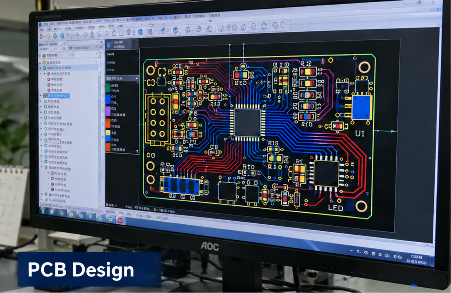
In-house design
Circuit and PCB layout developed around your product requirements.

Partner factory
Component placement and assembly for the approved board design.

Partner factory
Reflow soldering as part of the board assembly process.
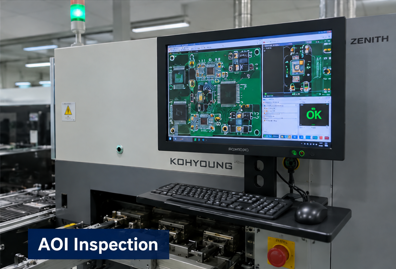
Partner factory
Optical inspection to support assembly quality checks.
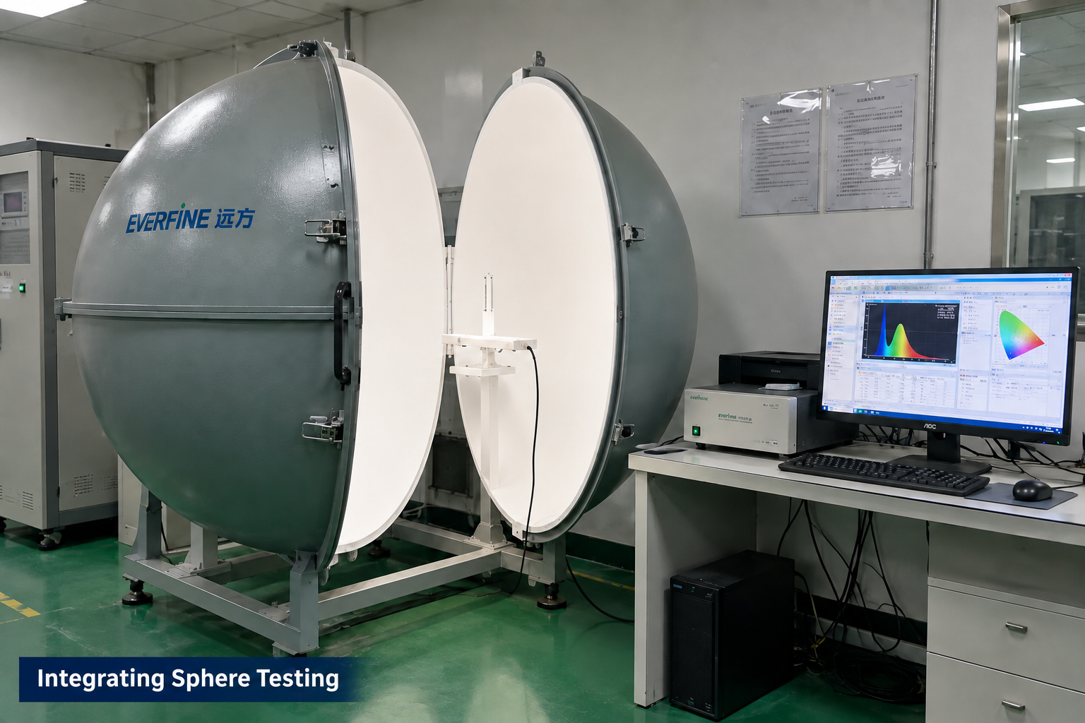
Partner factory
Optical measurement for applicable LED module projects.
Manufacturing and testing scope is agreed for each project. Integrating sphere testing applies to LED optical projects; it is not a required test for every control board. These images illustrate capabilities, not test results or certification for this product.
PROJECT QUESTIONS
These answers describe how a project can begin. They do not promise an unreviewed specification, performance result, certification, schedule, or price.
Send tank or chamber drawings, lamp position, water depth, flow, water conditions, exposed materials, electrical supply, maintenance access and safety controls. Define the treatment objective and validation method before selecting a lamp layout.
No. Radiant power alone does not establish delivered dose. Water volume or flow, UV transmittance, distance, geometry, mixing, shadowing, fouling, aging, exposure time, and the target microorganism must be included in system validation.
No. Never look directly at an operating UVC source or expose eyes or skin. Use a fully enclosed, opaque, interlocked system and disconnect power before opening it for inspection or service.
Submerged integration is subject to the approved immersion conditions, but active UVC should not directly expose fish, plants, users, or sensitive tank materials. A closed filter chamber or shielded circulation section is the safer direction.
No. Quartz is selected because it can transmit UVC. It separates the electronics from water but does not shield surrounding materials or users from the emitted radiation.
An IP rating applies to the enclosure and stated test configuration. Confirm immersion depth, duration, temperature, cable entry, sealing condition, and the applicable test report before using the rating in a project specification.
The two wavelength bands may serve different project functions, but their optical outputs and intended roles must be specified separately. Do not claim a performance improvement without complete-application test evidence.
No. It is an OEM light-source module. The finished equipment requires its own materials, electrical safety, exposure control, waterproofing, dose, microbiological performance, labeling, and market-specific approval assessment.
RECOMMENDED READING
A waterproof lamp does not establish tank-material compatibility. Review the confirmed plastic damage case, quartz transmission and exposure controls before finalizing the layout.
Read the UVC safety articlePROJECT INQUIRY
Include the application, confirmed inputs, preferred targets, expected quantity, target date, and available drawings, photos, files, or samples.
Inquiry about: UVC LED Modules