
Vehicle location
Door, dashboard, console, footwell, trim, or other position, with drawings, photos, and available space.
VEHICLE-SPECIFIC LIGHTING MODULES
Develop an automotive ambient LED module around a defined door, dashboard, console or interior location. Share the light-guide geometry, color target, electrical requirements and harness drawings so we can review board layout and vehicle-specific integration.
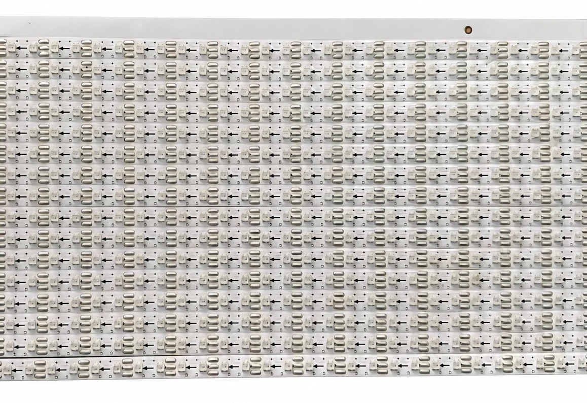
Rigid, shaped, or linear LED module geometry
Light-guide, diffuser, color, and uniformity coordination
Vehicle-specific power, interface, harness, and validation inputs
Review the inputs needed to start
↓APPLICATION FIRST
An automotive ambient lighting module must fit the trim, light guide, diffuser, harness, mounting points, and service path while also meeting the vehicle-specific electrical, thermal, vibration, material, EMC, and control requirements. A module for one platform should not be assumed suitable for another.
DEFINE BEFORE DESIGN
Confirmed requirements, preferred targets, and open questions can all be included in the first brief. Unknown values stay visible until they are reviewed.
Door, dashboard, console, footwell, trim, or other position, with drawings, photos, and available space.
LED color, CCT, RGB behavior, light guide or diffuser, illuminated length, uniformity, and viewing angle.
Supply range, current budget, driver relationship, dimming, startup, sleep, standby, and abnormal conditions.
Standalone, PWM, analog, LIN, CAN, UART, or other vehicle-specific commands and diagnostics.
PCB shape, mounting, connector, polarity, wire length, routing, strain relief, trim, and assembly sequence.
Temperature, vibration, moisture, materials, EMC priorities, lifetime target, test plan, and approval responsibility.
PROJECT FIT
These modules are developed for a defined vehicle location and integration scope rather than sold as universal-fit lighting parts.
Linear module geometry coordinated with guides, trim, harness, and multi-zone control.
Compact boards, diffusers, mounting, spill control, and connector access.
Distribution, glare control, dimming, mounting, wiring, and thermal conditions.
Flexible placement, harness routing, zones, color behavior, and assembly constraints.
CONTROLLED DEVELOPMENT PATH
A review result, prototype, or sample remains a project stage. Production begins only from the information and acceptance criteria approved for that project.
Confirm geometry, electrical input, optical target, thermal conditions, quantity, and the available source material.
Define the board, emitter arrangement, drive conditions, connections, mounting, and prototype route.
Review the agreed electrical, optical, thermal, mechanical, and safety-related acceptance points.
Carry the confirmed design, BOM, assembly, inspection, labeling, and packing information into production.
DESIGN & MANUFACTURING SUPPORT
Our in-house PCB design connects your product requirements with manufacturing and testing capabilities at our partner factories.
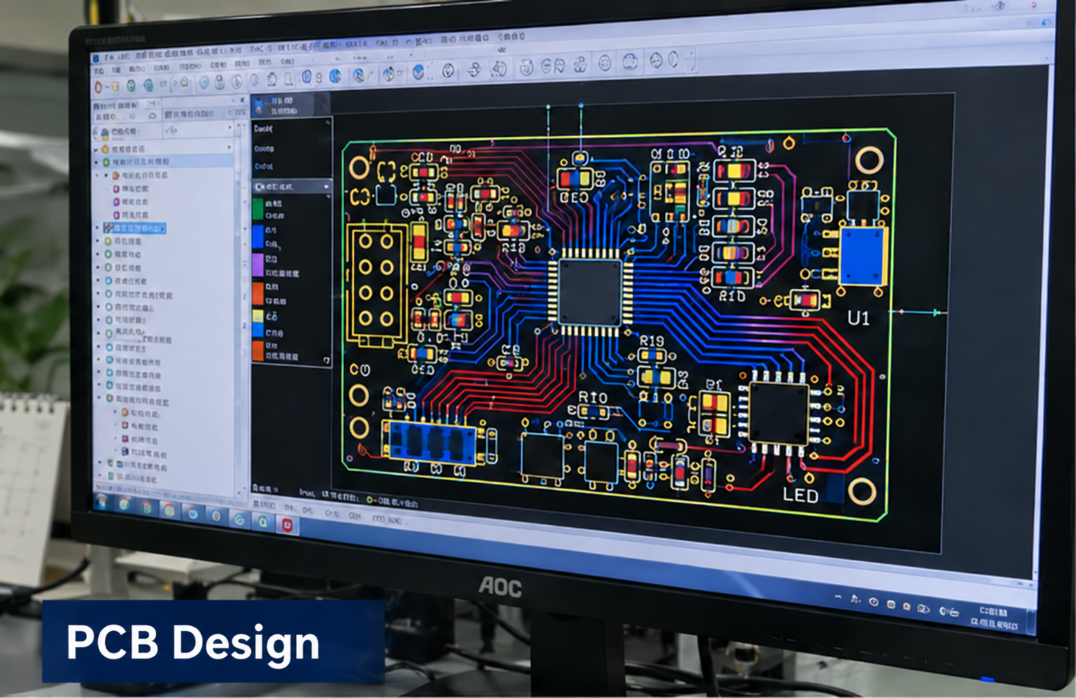
In-house design
Circuit and PCB layout developed around your product requirements.
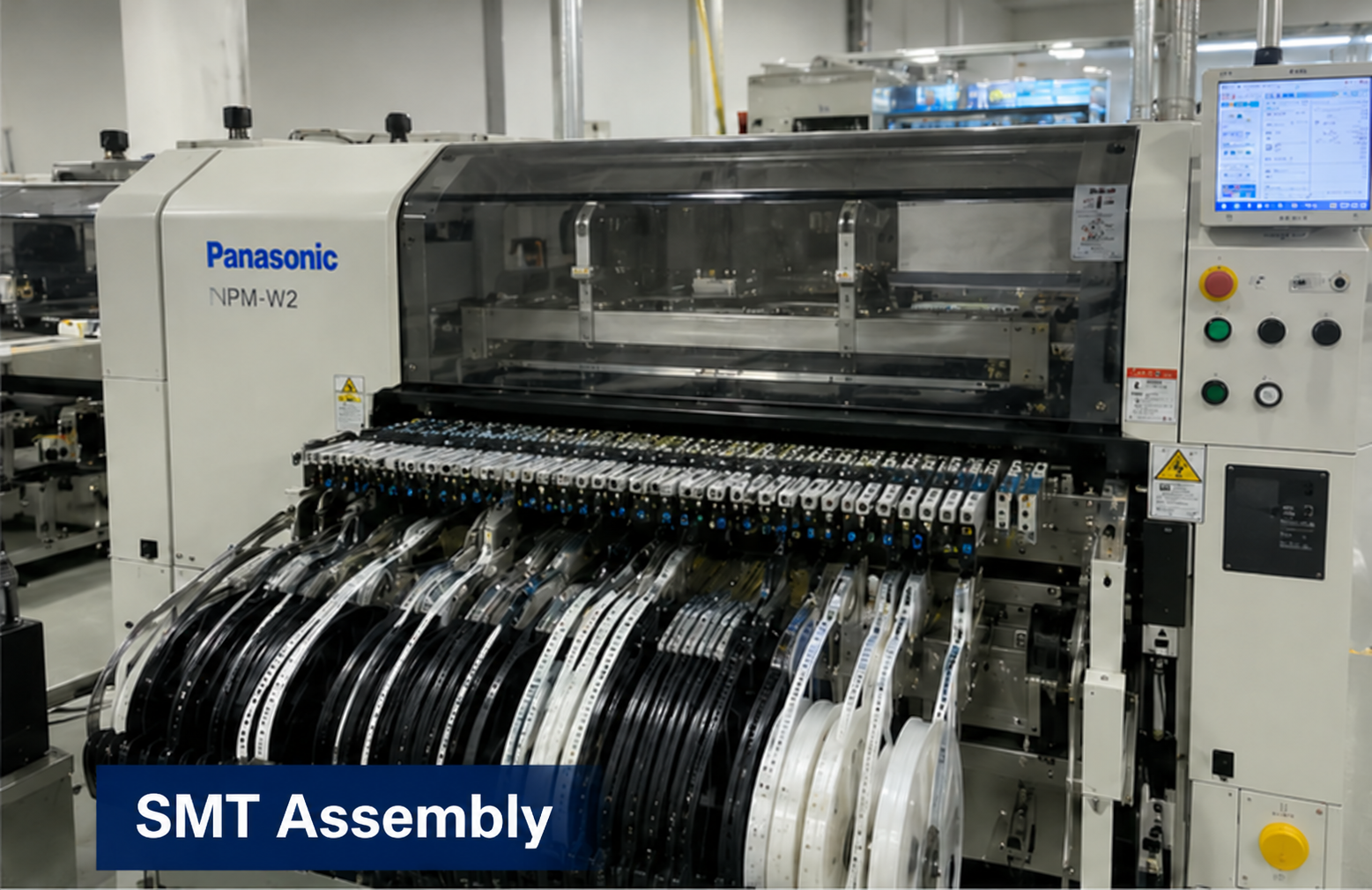
Partner factory
Component placement and assembly for the approved board design.
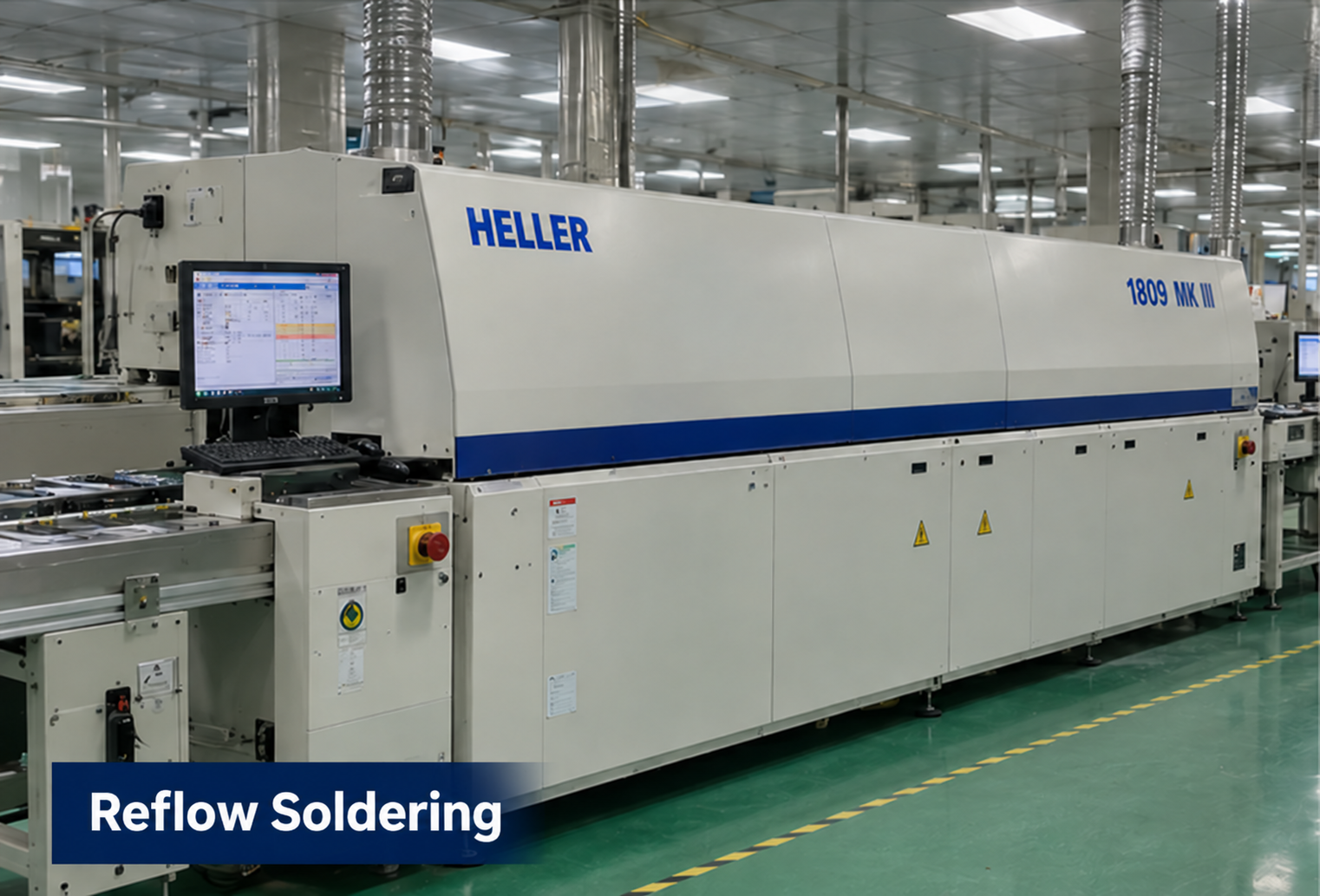
Partner factory
Reflow soldering as part of the board assembly process.
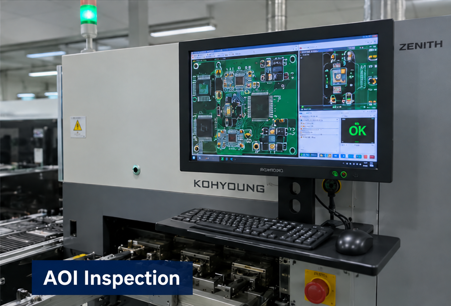
Partner factory
Optical inspection to support assembly quality checks.
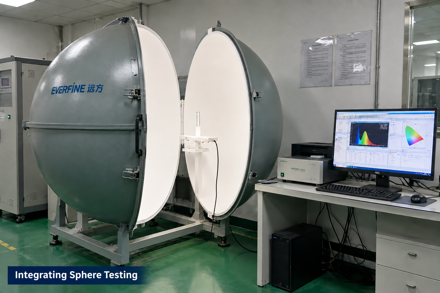
Partner factory
Optical measurement for applicable LED module projects.
Manufacturing and testing scope is agreed for each project. Integrating sphere testing applies to LED optical projects; it is not a required test for every control board. These images illustrate capabilities, not test results or certification for this product.
PROJECT QUESTIONS
These answers describe how a project can begin. They do not promise an unreviewed specification, performance result, certification, schedule, or price.
Rigid, segmented, or other module arrangements can be evaluated using the available geometry, mounting, optical path, wiring, manufacturing, and service constraints.
Color and animation can be included when the LED type, zone or pixel count, driver, control interface, timing, power budget, and accepted effect examples are defined.
No. Applicable standards, customer specifications, test responsibility, evidence, and approval status must be confirmed for the actual vehicle program and market.
Provide exact platform and location, drawings or photos, optical parts, power and communication requirements, harness and connector details, environment, quantity, target date, and required validation documents.
PROJECT INQUIRY
Include the application, confirmed inputs, preferred targets, expected quantity, target date, and available drawings, photos, files, or samples.
Inquiry about: Automotive Ambient Lighting Modules